


© National Instruments
|
2-19
Timing Engines and DSP Streams
This section gives an overview of the internal implementation of the NI PXIe-4302/4303 and the
limitations that exist on how the NI PXIe-4302/4303 can be configured. The use of NI-DAQmx
software allows you to easily configure the NI PXIe-4302/4303 without you needing in depth
knowledge about the internal workings of hardware. However, there are limitations in the way
in which the NI PXIe-4302/4303 can be configured and to understand them requires some
explanation about what is happening in hardware.
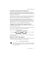
Timing Engines
When you create a task in software, that software task interacts with one or more timing engines
in the NI PXIe-4302/4303. There are a total of four timing engines in hardware that can be
operated simultaneously. Each of these timing engines can have individualized configuration
settings for timing, triggering, and the sample mode. Depending on the sample mode selected,
the timing engine will use either a buffered mode or hardware-timed single point DSP stream.
DSP Streams
The DSP streams in the NI PXIe-4302/4303 perform the digital signal processing on the
acquired data before sending the data to software. There are two types of DSP streams: buffered
mode streams and hardware-timed single point streams. The NI PXIe-4302/4303 has
four streams for each of these types and each stream can handle up to 8 channels. Therefore, it
is possible to use all 32 channels in either buffered mode or hardware-timed single point mode.
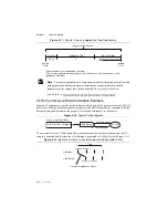
AI Channels and DSP Streams
While all 32 analog input channels are simultaneously digitized by their ADC, the controls of
the ADCs are grouped into four banks of eight. The configuration of the ADCs is different for
buffered mode and hardware-timed single point mode, and as a result, there are limitations on
how channels can be used when both buffered and hardware-timed single point tasks operate
simultaneously. Analog input channels in the following banks must all be configured for either
buffered mode or hardware-timed single point mode: ai0:7, ai8:15, ai16:23, and ai24:31.
To allow greater flexibility in how the NI PXIe-4302/4303 can be configured, a cross-point
switch exists between the ADCs and the DSP streams. This cross-point switch allows a single
DSP stream to use any eight of the 32 analog input channels, as long as the ADC for the analog
input channel selected is configured for the same mode as the DSP stream. Once an analog input
channel is used in a task, it is not available for use in other tasks.
Examples of Limitations
The following configuration scenarios will cause errors:
•
A task is setup and started using ai0 in buffered mode. A second task is created with ai1 in
hardware-timed single point mode. The second task will produce an error since the first task
has already placed ai0:7 in buffered mode and therefore ai1 cannot be used in
hardware-timed single point mode.


