background image

© National Instruments

|

ix

About This Manual

The 

PXI-1036/PXI-1036DC User Manual

 contains information about installing, configuring, 

using, and maintaining the PXI-1036 and PXI-1036DC chassis.

Note

For PXI-1036/PXI-1036DC specifications, refer to the 

PXI-1036/PXI-1036DC Specifications

 on 

ni.com

.

Related Documentation

The following documents contain information that you might find helpful as you read this 
manual:

PXI-1031DC/1036DC DC Cable Kit Installation Guide

CompactPCI Specification PICMG 2.0 R 3.0

PXI Hardware Specification

PXI Software Specification

IEEE 1101.1-1991, 

IEEE Standard for Mechanical Core Specifications for 

Microcomputers Using IEC 603-2 Connectors

IEEE 1101.10, 

IEEE Standard for Additional Mechanical Specifications for 

Microcomputers Using IEEE 1101.1 Equipment Practice

Summary of Contents for PXI-1036

Page 1: ...PXI PXI 1036 PXI 1036DC User Manual PXI 1036 PXI 1036DC User Manual December 2019 371550F 01...

Page 2: ...port phone numbers email addresses and current events National Instruments Corporate Headquarters 11500 North Mopac Expressway Austin Texas 78759 3504 USA Tel 512 683 0100 For further support informat...

Page 3: ...e encouraged to try to correct the interference by one or more of the following measures Reorient the antenna of the receiver the device suffering interference Relocate the transmitter the device gene...

Page 4: ...TLE OR NON INFRINGEMENT AND ANY WARRANTIES THAT MAY ARISE FROM USAGE OF TRADE OR COURSE OF DEALING NI DOES NOT WARRANT GUARANTEE OR MAKE ANY REPRESENTATIONS REGARDING THE USE OF OR THE RESULTS OF THE...

Page 5: ...ependent from NI and have no agency partnership or joint venture relationship with NI Patents For patents covering NI products technology refer to the appropriate location Help Patents in your softwar...

Page 6: ...with CompactPCI 1 6 System Controller Slot 1 6 Star Trigger Slot 1 7 Peripheral Slots 1 7 Local Bus 1 7 Trigger Bus 1 8 System Reference Clock 1 8 Chapter 2 Installation and Configuration Safety Infor...

Page 7: ...Trigger Configuration in MAX 2 10 Using System Configuration and Initialization Files 2 10 Chapter 3 Maintenance DC Fuse Replacement PXI 1036DC Only 3 1 Service Interval 3 1 Preparation 3 1 Cleaning 3...

Page 8: ...ed Documentation The following documents contain information that you might find helpful as you read this manual PXI 1031DC 1036DC DC Cable Kit Installation Guide CompactPCI Specification PICMG 2 0 R...

Page 9: ...s are undamaged Inspect the inner chassis for any possible damage debris or detached components If damage appears to have been caused during shipment file a claim with the carrier Retain the packing m...

Page 10: ...e of applications The key features of the chassis include the following Accepts 3U PXI and CompactPCI PICMG 2 0 R 3 0 modules 6 slot chassis with universal AC input and automatic voltage frequency ran...

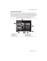
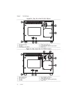
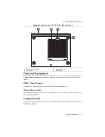
Page 11: ...s name stenciled on the face plate Figure 1 2 shows the rear view of the PXI 1036 Figure 1 3 shows the rear panel of the PXI 1036DC Figure 1 4 shows the bottom of the chassis both types of chassis wil...

Page 12: ...is 1 Rear Exhaust Vents 2 AC Input 3 Power Supply Fan Exhaust 4 Chassis Ground Screw 5 AUTO HIGH Fan Speed Selector Switch 6 Rubber Foot 1 Rear Exhaust Vents 2 DC Fuse Socket 3 DC Input 4 AC Input 5 P...

Page 13: ...C Filler Panels Optional EMC filler panel kits are available from National Instruments Rack Mount Kits A rack mount kit option is available for mounting the PXI 1036 or PXI 1036DC chassis into a 19 in...

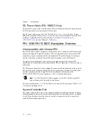
Page 14: ...sis The signals on the backplane P1 connectors meet the requirements of the CompactPCI specification for both peripheral and system modules Refer to Appendix A Pinouts for pinout information The PXI s...

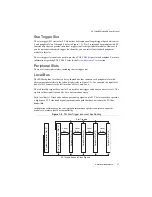
Page 15: ...y chained bus that connects each peripheral slot with adjacent peripheral slots to the left and right refer to Figure 1 5 For example the right local bus of slot 2 connects to the left local bus of sl...

Page 16: ...lling System Reference Clock The PXI 1036 PXI 1036DC supplies the PXI 10 MHz system clock signal PXI_CLK10 independently to each peripheral slot An independent buffer having a source impedance matched...

Page 17: ...ircuits Operating personnel and service personnel must not remove protective covers when operating or servicing the chassis Adjustments and service to internal components must be undertaken by qualifi...

Page 18: ...power supply enters the front and left side of the chassis which is shown in Figure 1 1 Front View of the PXI 1036 Chassis then exits through the rear of the chassis which is shown in Figure 1 2 Rear...

Page 19: ...an instrument rack Note You may want to remove the feet from the chassis when rack mounting To do so remove the screws holding the feet in place Connecting Safety Ground Caution The PXI 1036 PXI 1036D...

Page 20: ...able supplied Refer to Figure 1 2 Rear View of the PXI 1036 Chassis or to Figure 1 3 Rear View of the PXI 1036DC Chassis to locate the AC inlet The power switch allows you to power on the chassis or p...

Page 21: ...contacts part number FS4008D choice of solder cup or crimp terminals Use of UL listed AWG 10 wire is recommended maximum length 216 in Install an F30A 500 VDC 600 VAC 1 5 in 41 in 10 mm 38 mm Midget...

Page 22: ...assis power switch is in the Off Standby position Caution To protect both yourself and the chassis from electrical hazards leave the chassis off until you finish installing the controller 2 Install th...

Page 23: ...that the controller boots If the controller does not boot refer to your controller user manual Figure 2 4 shows a PXI controller installed in the system controller slot of a PXI 1036 PXI 1036DC chass...

Page 24: ...5 Slide the module to the rear of the chassis making sure that the injector ejector handle is pushed down as shown in Figure 2 3 3 When you begin to feel resistance push up on the injector ejector han...

Page 25: ...to expand it 3 If the PXI system controller has not yet been configured it will be labeled PXI System Unidentified Right click this entry to display the context menu and then select the appropriate c...

Page 26: ...ws many combinations of PXI chassis and system modules To assist system integrators the manufacturers of PXI chassis and system modules must document the capabilities of their products The minimum doc...

Page 27: ...t out from the chassis Service Interval Clean dust from the chassis exterior and interior as needed based on the operating environment Periodic cleaning increases reliability Preparation The informati...

Page 28: ...xterior Cleaning Cautions Avoid getting moisture inside the chassis during exterior cleaning especially through the top vents Use just enough moisture to dampen the cloth Do not wash the front or rear...

Page 29: ...oller slot Table A 2 shows the P2 J2 connector pinout for the System Controller slot Table A 3 shows the P1 J1 connector pinout for the star trigger slot Table A 4 shows the P2 J2 connector pinout for...

Page 30: ...GND SERR GND 3 3 V PAR C BE 1 GND 17 GND 3 3 V IPMB_SCL IPMB_SDA GND PERR GND 16 GND DEVSEL GND V I O STOP LOCK GND 15 GND 3 3 V FRAME IRDY GND TRDY GND 12 14 Key Area 11 GND AD 18 AD 17 AD 16 GND C...

Page 31: ...G7 GND 15 GND PXI_BRSVA15 GND FAL REQ5 GNT5 GND 14 GND BP I O BP I O BP I O GND BP I O GND 13 GND BP I O GND V I O BP I O BP I O GND 12 GND BP I O BP I O BP I O GND BP I O GND 11 GND BP I O GND V I O...

Page 32: ...SERR GND 3 3 V PAR C BE 1 GND 17 GND 3 3 V IPMB_SCL IPMB_SDA GND PERR GND 16 GND DEVSEL GND V I O STOP LOCK GND 15 GND 3 3 V FRAME IRDY BD_SEL TRDY GND 12 14 Key Area 11 GND AD 18 AD 17 AD 16 GND C B...

Page 33: ...LK10 GND 16 GND PXI_TRIG1 PXI_TRIG0 RSV GND PXI_TRIG7 GND 15 GND PXI_BRSVA15 GND RSV PXI_STAR6 PXI_LBR6 GND 14 GND RSV RSV RSV GND RSV GND 13 GND RSV GND V I O RSV RSV GND 12 GND RSV RSV RSV GND RSV G...

Page 34: ...ND SERR GND 3 3 V PAR C BE 1 GND 17 GND 3 3 V IPMB_SCL IPMB_SDA GND PERR GND 16 GND DEVSEL GND V I O STOP LOCK GND 15 GND 3 3 V FRAME IRDY BD_SEL TRDY GND 12 14 Key Area 11 GND AD 18 AD 17 AD 16 GND C...

Page 35: ...XI_CLK10 GND 16 GND PXI_TRIG1 PXI_TRIG0 RSV GND PXI_TRIG7 GND 15 GND PXI_BRSVA15 GND RSV PXI_LBL6 PXI_LBR6 GND 14 GND RSV RSV RSV GND RSV GND 13 GND RSV GND V I O RSV RSV GND 12 GND RSV RSV RSV GND RS...

Page 36: ...y your systems accuracy and reliability requirements and provides warranty sparing and calibration services to help you maintain accuracy and minimize downtime over the life of your system Visit ni co...

Page 37: ...tions Engineers make sure every question submitted online receives an answer Software Support Service Membership The Standard Service Program SSP is a renewable one year subscription included with alm...

Page 38: ...ake figure 2 2 filler panel installation 2 3 setting fan speed 2 2 D DC power cable 1 6 power up testing 2 4 documentation conventions used in manual ix related documentation x E EMC filler panel kit...

Page 39: ...overview 1 7 P1 J1 connector pinouts table A 6 P2 J2 connector pinouts table A 7 pinouts A 1 P1 J1 connector peripheral slot table A 6 star trigger slot table A 4 system controller slot table A 2 P2 J...

Page 40: ...s 1 2 optional equipment 1 5 P1 DC input connector figure 2 4 rack mount kits 1 5 rack mounting 2 3 rear view of chassis 1 4 safety ground connecting 2 3 R rack mount kits 1 5 rack mounting 2 3 relate...

Reviews: