© National Instruments
|
2-3
PXI-1036/PXI-1036DC User Manual
Setting Fan Speed
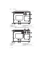
The AUTO/HIGH fan-speed selector switch is on the rear panel of the PXI-1036 and
PXI-1036DC. Refer to Figure 1-2,
Rear View of the PXI-1036 Chassis
, to locate the fan-speed selector switch. Select HIGH for maximum
cooling performance (recommended) or AUTO for quieter operation. The fan speed is
determined by chassis intake air temperature when set to AUTO.
Installing Filler Panels
To improve module cooling performance, install filler panels (provided with the chassis) in
unused or empty slots. Secure with the captive mounting screws provided.
Rack Mounting
Rack mount applications require the optional rack mount kits available from National
Instruments. Refer to the
PXI-1036/PXI-1036DC Specifications
and the instructions
supplied with the rack mount kits to install your chassis in an instrument rack.
Note
You may want to remove the feet from the chassis when rack mounting. To
do so, remove the screws holding the feet in place.
Connecting Safety Ground
Caution
The PXI-1036/PXI-1036DC chassis is designed with a three-position
inlet that connects the cord set ground line to the chassis ground. To minimize shock
hazard, make sure the electrical power outlet you use to power the chassis has an
appropriate earth safety ground.
For DC powered applications, or if your power outlet does not have an appropriate ground
connection, you must connect the premise safety ground to the chassis grounding screw located
on the rear panel. Refer to Figure 1-2,
Rear View of the PXI-1036 Chassis
View of the PXI-1036DC Chassis
, to locate the chassis grounding screw. Complete the following
steps to connect the safety ground.
1.
Connect a 10 AWG (2.6 mm) wire to the chassis grounding screw using a grounding lug.
The wire must have green insulation with a yellow stripe or must be noninsulated (bare).
2.
Attach the opposite end of the wire to permanent earth ground using toothed washers or a
toothed lug.

