background image

4

|

ni.com

|

NI 9503 C Series Stepper Drive Modules and SoftMotion Module 

SoftMotion Module Overview

SoftMotion Module UDV axes allow you to implement an interface for communication between 
the SoftMotion Engine and the LabVIEW FPGA Module. This is achieved using user-defined 
variables that you add to the project, making it easier to use C Series modules in FPGA mode 
with the SoftMotion Module. 

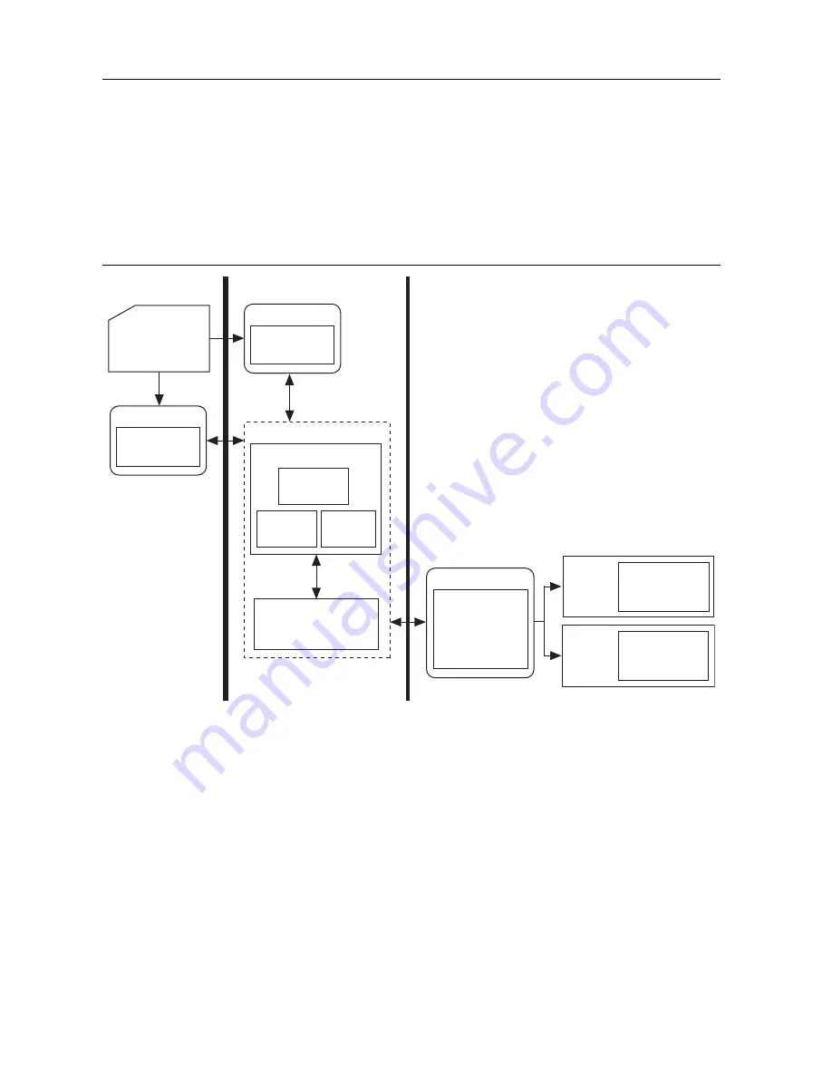
The following figure shows the SoftMotion architecture when you use the SoftMotion Module 
with UDV axes and the LabVIEW FPGA Module.

Figure 2.  

SoftMotion Module with UDV Axes

You use the LabVIEW Project to configure your axis settings and test your configuration. When 
your hardware configuration is complete, you use SoftMotion APIs to create move profiles. 

Communication to the LabVIEW FPGA Module is handled through user-defined variables. You 
use the SoftMotion Drive Interface VIs to implement an interface for communication between 
the SoftMotion Engine and the LabVIEW FPGA Module. When you use the Drive Interface VIs 
with UDV axes you communicate using a predefined set of UDVs. Refer to 

Adding 

User-Defined Variables for Use With a UDV Axis

 in the 

SoftMotion Module Help, 

available by 

selecting 

Help»LabVIEW Help

 for information about the predefined UDVs. Refer to the 

Using 

NI 9503 with SoftMotion

 section for more information about the NI SoftMotion Drive 

Interface VIs.

Axi

s

Interf

a

ce

Tr

a

jectory

Gener

a

tor

Su

pervi

s

ory

Control

Ho

s

t HMI 

a

nd

Axi

s


S

etting

s

:

L

a

bVIEW Project

Non Real-Time

LabVIEW Real-Time Module

NI SoftMotion

U

s

er VI

NI 

S

oftMotion 

API

s

LabVIEW FPGA with 
NI Scan En

g

ine Supported Platform

S

erie

s

Mod

u

le(

s

)

cRIO 

Ch

ass

i

s

Motor Control, 

Drive Interf

a

ce,

a

nd 

S

ync VI

s

cRIO

Ch

ass

i

s

NI 950x

S

erie

s

Mod

u

le(

s

)

U

s

er-Defined V

a

ri

a

ble

Comm

u

nic

a

tion

Mod

u

le

U

s

er VI

NI 

S

oftMotion 

API

s

U

s

er VI

NI 

S

oftMotion Engine

Summary of Contents for NI 9503 C Series

Page 1: ...ents What You Need to Get Started 2 Hardware 2 Software 3 SoftMotion Module Overview 4 Hardware and Software Installation 5 Step 1 Set Up the Real Time System 5 Step 2 Connect NI 9503 to the Stepper M...

Page 2: ...NI C Series Drive Modules at zone ni com for more information Ethernet connection and cable for the CompactRIO controller NI or third party stepper motor Note NI offers NEMA 17 and NEMA 23 stepper mo...

Page 3: ...abVIEW 2014 Real Time Module or later LabVIEW 2014 FPGA Module or later LabVIEW 2014 SoftMotion Module or later NI RIO Device Drivers 2014 or later Figure 1 shows the system setup without optional har...

Page 4: ...h user defined variables You use the SoftMotion Drive Interface VIs to implement an interface for communication between the SoftMotion Engine and the LabVIEW FPGA Module When you use the Drive Interfa...

Page 5: ...ave HSI support only on slots 1 through 4 Refer to your chassis documentation for more information about HSI support Step 2 Connect NI 9503 to the Stepper Motor 1 Connect the stepper motor to the NI 9...

Page 6: ...Software on and Configure the NI RT Controller This step covers installing and configuring the software for the NI 9503 stepper drive module It assumes that all required software from the What You Ne...

Page 7: ...EW project and contains all required UDVs for use with the NI 9503 1 Select File Create Project Sample Projects SoftMotion Stepper Drive NI 9503 to access the sample project provided for the NI 9503 2...

Page 8: ...the VI 3 Select Window Show Block Diagram to open the FPGA VI block diagram The following table briefly describes each FPGA VI loop used in the project Table 1 Stepper Drive Getting Started UDV Descri...

Page 9: ...the LabVIEW FPGA Module The transferred data is written to FPGA memory and accessed using the Read Motion Memory and Write Motion Memory Drive Interface VIs This loop is required to be implemented as...

Page 10: ...Axis Configuration dialog box for NI 9503 UDV axes Refer to the NI SoftMotion Module section of the LabVIEW Help for detailed information about each configuration option Figure 6 Axis Configuration Di...

Page 11: ...un button 7 Right click the axis in the Project Explorer window and select Interactive Test Panel from the shortcut menu Note If the Scan Engine was not automatically transitioned from Configuration t...

Page 12: ...the additional modules and what they are used for in the Stepper Drive with Encoder example Table 4 Additional C Series Modules Used in the Stepper Drive with Encoder Example C Series Module Slot Numb...

Page 13: ...Install and connect an NI 9472 digital output module in slot 3 of the chassis 2 Connect digital output devices to the NI 9472 3 Connect the NI 9472 to the NI PS 16 power supply a Connect an available...

Page 14: ...1 also provides a 5 V supply for encoder power The Stepper Drive with Encoder example uses the following NI 9411 signals for the corresponding encoder signals 3 Connect the NI 9411 to the NI PS 16 pow...

Page 15: ...tal inputs 0 through 3 Axis 1 DIO Control Port B Contains the values of digital outputs 4 through 7 as well as information to enable position compare and position capture operations and clear input la...

Page 16: ...the encoder velocity using the user specified filter settings and returns the feedback position and filtered velocity feedback information to the SoftMotion Engine Encoder Loop The encoder loop uses t...

Page 17: ...oller NI 9503 Operating Instructions and Specifications Use this document to learn how to use the National Instruments 9503 including specifications and pin assignments for the NI 9503 NI 9411 Operati...

Page 18: ...is your complete resource for technical support At ni com support you have access to everything from troubleshooting and application development self help resources to email and phone assistance from...

Reviews: