
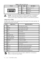
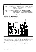

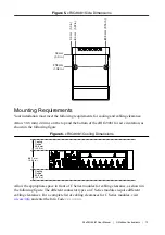

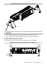
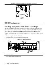

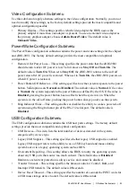

Figure 5.
cRIO-9081 Side Dimensions
27.6 mm
(1.08 in.)
27.6 mm
(1.08 in.)
0.0 mm
(0.0 in.)
0.0 mm
(0.0 in.)
0.0 mm (0.0 in.)0.0 mm (0.0 in.)
8.0 mm (0.32 in.)8.0 mm (0.32 in.)
80.0 mm (3.15 in.)80.0 mm (3.15 in.)
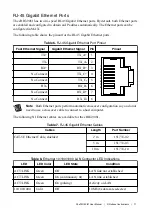
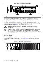
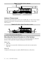
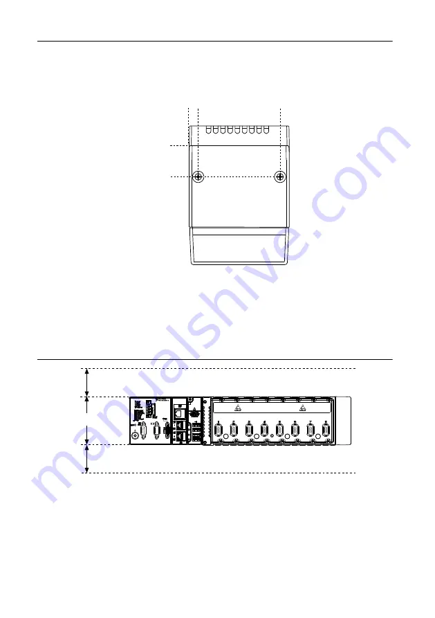
Mounting Requirements
Your installation must meet the following requirements for cooling and cabling clearance.
Allow 50.8 mm (2.00 in.) on the top and the bottom of the cRIO-9081 for air circulation, as
shown in the following figure.
Figure 6.
cRIO-9081 Cooling Dimensions
Cooling
Outline
50.8 mm
(2.00 in.)
Cooling
Outline
50.8 mm
(2.00 in.)
88.1 mm
(3.43 in.)
NI cRIO-9081
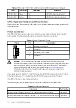
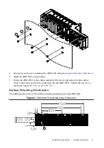
Allow the appropriate space in front of C Series modules for cabling clearance, as shown in
the following figure. The different connector types on C Series modules require different
cabling clearances. For a complete list of cabling clearances for C Series modules, visit
and enter the Info Code
crioconn
.
NI cRIO-9081 User Manual
|
© National Instruments
|
19