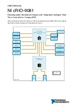
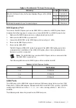
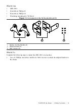
Table 5.
USB Host Port Pinout
Pinout
Pin
Signal
Description
1
4
2
3
1
VCC
Cable power (5 V)
2
D-
USB data-
3
D+
USB data+
4
GND
Ground
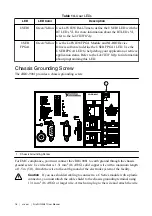
Caution
Do not hot-swap USB devices while the cRIO-9081 is in a hazardous
location or connected to high voltages. If the cRIO-9081 is not in a hazardous
location, you can connect and disconnect USB devices without affecting operation.
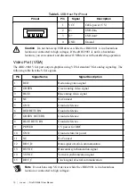
Video Port (VGA)
The cRIO-9081 VGA port outputs graphics using VESA standard VGA analog signaling. The
following table lists the VGA signals.
Pin
Signal Name
Signal Description
1
RED
Red analog video signal
2
GREEN
Green analog video signal
3
BLUE
Blue analog video signal
4
NC
No Connect
5
GND
Ground reference
6
RED RETURN
Ground reference
7
GREEN RETURN
Ground reference
8
BLUE RETURN
Ground reference
9
POWER
5 V power for DDC
10
GND
Ground return for power
11
NC
No Connect
12
DDC_D
Data signal of serial communication
13
HSYNC
Horizontal synchronization signal
14
VSYNC
Vertical synchronization signal
15
DDC_C
Clock signal of serial communication
Note
Do not hot-swap VGA devices while the cRIO-9081 is in a hazardous
location or connected to high voltages.
10
|
ni.com
|
NI cRIO-9081 User Manual


