

cRIO-FRC Operating Instructions and Specifications
12
ni.com
Using the Internal Real-Time Clock
The system clock of the cRIO-FRC is synchronized with the internal
high-precision real-time clock at startup. This synchronization provides
timestamp data to the controller. You can also use the internal real-time
clock to correct drift of the system clock. Refer to the
Internal Real-Time
Clock
specification in the
Specifications
section for the accuracy
specifications of the real-time clock.
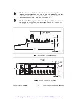
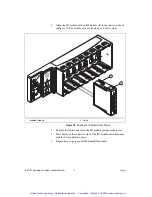
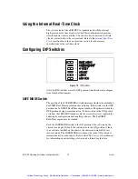
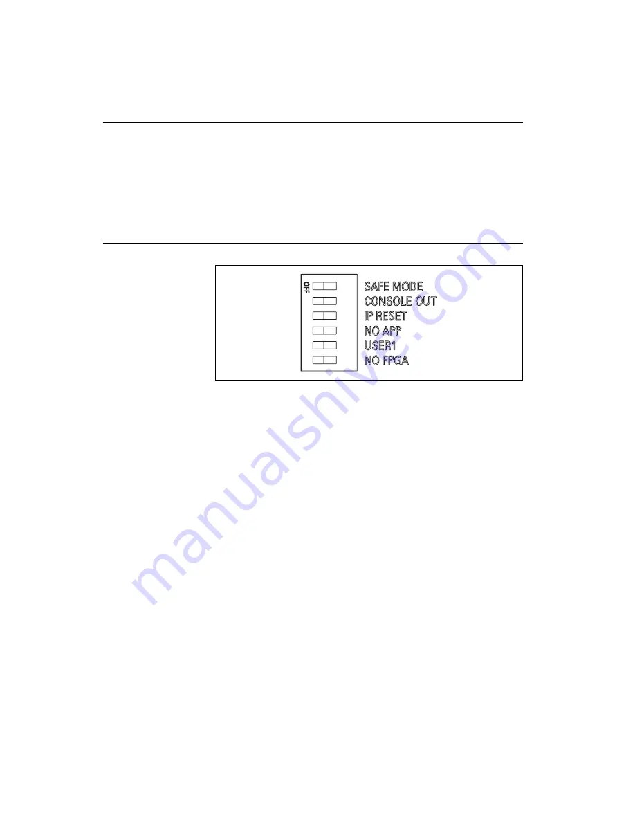
Configuring DIP Switches
Figure 12.
DIP Switches
All of the DIP switches are in the OFF position when the chassis is shipped
from National Instruments.
SAFE MODE Switch
The position of the SAFE MODE switch determines whether the embedded
LabVIEW Real-Time engine launches at startup. If the switch is in the OFF
position, the LabVIEW Real-Time engine launches. Keep this switch in the
OFF position during normal operation. If the switch is in the ON position
at startup, the cRIO-FRC launches only the essential services required for
updating its configuration and installing software. The LabVIEW
Real-Time engine does not launch.
Push the SAFE MODE switch to the ON position if the software on the
chassis is corrupted. Even if the switch is not in the ON position, if there
is no software installed on the chassis, the chassis automatically boots
into safe mode. The SAFE MODE switch must be in the ON position to
reformat the drive on the chassis. Refer to the
FRC Control System Manual
for information about installing software and reformatting the drive.
1 6
5
4
3
2
Artisan Technology Group - Quality Instrumentation ... Guaranteed | (888) 88-SOURCE | www.artisantg.com