background image

©

 National Instruments Corporation

11

USB-6525 User Guide and Specifications 

closed, current flows through both the load and the USB-6525 optocoupler, 
and the USB-6525 registers a logic high for the channel.

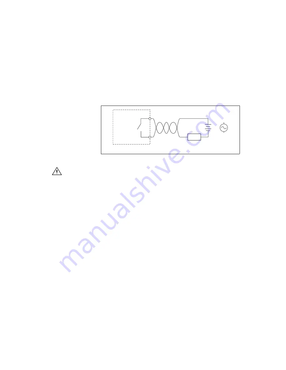
Solid-State Relay (SSR) Outputs

You can connect loads to the USB-6525. Connect the load to one of the 
leads of the power source. Connect either the P0.

x

A or the P0.

x

B terminal 

to the load and the other terminal to the other lead of the AC or DC power 
source. Figure shows a possible configuration where the load is 
connected to the P0.

x

B terminal and the DC or AC power source.

Figure 7.  

Connecting a Load to the USB-6525

Caution

Use twisted-pair field wiring to reduce EMC noise.

Power-On and Power-Off Conditions

The default power-on state of the solid-state relays is open. By default, the 
solid-state relays remain open when the chassis and the USB-6525 device 
are powered off.

Protecting Inductive Loads

When inductive loads are connected to the USB-6525 SSR outputs, a large 
counter-electromotive force may occur at switching time because of the 
energy stored in the inductive load. These flyback voltages can damage the 
SSR outputs and/or the external power supply.

Limit flyback voltages at your inductive load by installing one of the 
following:

For DC loads—Install a flyback diode within 18 in. of the load.

For AC loads—Install a metal oxide varistor (MOV) rated for 30 V

rms


or slightly higher.


_ or

AC

U

S

B-6525

P0.

x

 A

P0.

x

B

Lo

a

d

Twisted-P

a

ir

Wiring

Summary of Contents for 779640-01

Page 1: ...ata acquisition DAQ device Introduction The NI USB 6525 is a full speed USB 2 0 device that provides eight 60 VDC channel to channel isolated digital inputs DI eight 60 VDC 30 Vrms channel to channel...

Page 2: ...s Getting Started Guide that shipped with your device and is also accessible from Start All Programs National Instruments NI DAQ for more information Note For information about non Windows operating s...

Page 3: ...You can apply the signal labels on the screw terminal blocks for easy signal identification 2 Refer to Table 1 and Figure 4 for label orientation and affix provided signal labels to the screw terminal...

Page 4: ...auge between 16 AWG 28 AWG Table 1 Digital Terminal Assignments Module Terminal Signal Module Terminal Signal 1 P0 0A 17 P1 0 2 P0 0B 18 P1 0 3 P0 1A 19 P1 1 4 P0 1B 20 P1 1 5 P0 2A 21 P1 2 6 P0 2B 22...

Page 5: ...specified interval Intermediate length pulses pulses longer than half of the interval but less than the interval may or may not pass the filter The filter operates on the inputs from the optocouplers...

Page 6: ...equal to one half of the specified timing interval The input signal is sampled on each rising edge of the sample clock which is every 40 s1 A change in the input signal is recognized only if it mainta...

Page 7: ...ou can program the NI 6525 to send an interrupt when a change occurs on any input line The NI 6525 can monitor changes on selected input lines or on all input lines It can monitor for rising edges 0 t...

Page 8: ...g edges on the sensor which correspond to over limit conditions Bit 0 is connected to a switch The software can react to any switch closure which is represented by a falling edge If the switch closure...

Page 9: ...set software command within the time specified for the watchdog timer the outputs go to a user defined safe state and remain in that state until the watchdog timer is disarmed by the application and n...

Page 10: ...tions for a power supply and load connected to an isolated input Figure 6 Connecting a Power Supply and Load to the Isolated Input Caution Use twisted pair field wiring to reduce EMC noise In Figure 6...

Page 11: ...ution Use twisted pair field wiring to reduce EMC noise Power On and Power Off Conditions The default power on state of the solid state relays is open By default the solid state relays remain open whe...

Page 12: ...ct DC inductive loads and an MOV to protect AC inductive loads respectively Figure 8 Contact Protection for DC Inductive Loads Figure 9 Contact Protection for AC Inductive Loads Inductive Load USB 652...

Page 13: ...an RL value small enough to provide the necessary source current but large enough to reduce sink current and to avoid consuming unnecessary power Many TTL level applications use an RL value of 5 k Ev...

Page 14: ...ypical Solid State Relay Outputs Number of output channels 8 ch ch isolated Relay type Normally open solid state relay SSR Switching voltage 60 VDC 30 Vrms max Switching current per channel 500 mA max...

Page 15: ...state Active current 150 mA max Suspend current 350 A typ Physical Characteristics Dimensions Without connectors 6 35 cm 8 51 cm 2 31 cm 2 50 in 3 35 in 0 91 in With connectors 8 18 cm 8 51 cm 2 31 cm...

Page 16: ...60 VDC continuous Withstand 60 VDC continuous Caution Do not use this module for connection to signals or for measurements within Measurement Categories II III or IV Hazardous Locations The USB 6525 i...

Page 17: ...ows 2006 95 EC Low Voltage Directive safety 2004 108 EC Electromagnetic Compatibility Directive EMC Online Product Certification Refer to the product Declaration of Conformity DoC for additional regul...

Page 18: ...nd cables specified in the installation instructions You must have all covers and filler panels installed during operation of the device Do not operate the device in an explosive atmosphere or where t...

Page 19: ...e measurements include signal levels special equipment limited energy parts of equipment circuits powered by regulated low voltage sources and electronics Measurement Category II is for measurements p...

Page 20: ...an obtain the DoC for your product by visiting ni com certification If your product supports calibration you can obtain the calibration certificate for your product at ni com calibration National Inst...

Reviews: