National Cycle, Inc.
PO Box 158 Maywood, IL 60153-0158 USA
P: 708-343-0400 / F: 708-343-0625 / E: [email protected]
www.nationalcycle.com
©2021 National Cycle, Inc.
Page 04 of 13
10-118625-000 03/21
PREPARATION AND ELECTRICAL WIRING; CONT’D.
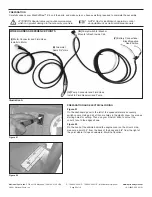
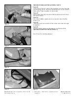
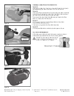
Figure 10
Take the Wire Harness and Switch
(F)
and locate the end of the Rubber
Hose and the Nylon 2-Pin Pump Connector with red and black wires (see
Illustration A
).
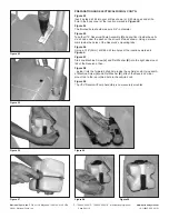
Figure 11
Take the harness sheath with the red/black wires and Quick-Connector and
fold it against the sheath with the Rubber Hose, as shown. Secure the two
sheaths with a Wire Tie
(M)
and trim the excess tie with wire cutters.
Figure 12
Insert these wire-tied Harness components under the vehicle’s left (driver’s
side) wheel cover and towards the interior cab’s dash panel.
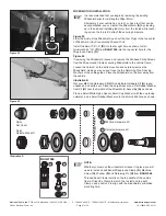
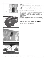
Figure 13
Keep pushing the wire-tied Harness components until they emerge under
the dash above the cab’s floorboards.
Figure 14
Move inside the cab and pull the wire-tied Harness components until you
can connect the Rubber Hose to the bottom of the Reservoir’s Electrical
Pump. Then push the Nylon Quick-Connector onto the two pins on top of
the Reservoir’s Electrical Pump.
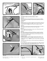
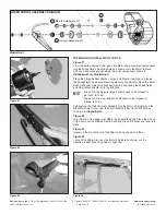
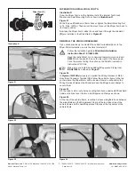
Figures 15A, 15B
Pull the Wire Harness Terminal
(I)
(single sheath with Small Nylon 2-Pin
Electrical Quick-Connector and a Rubber Hose) through the 3/4" hole cut
into the vehicle’s body in
Figures 3-4
, and seat the Harness Grommet
(II)
in that hole.
Into the end of the Rubber Hose, insert the Inline Check Valve
(E)
with the
arrow pointed
up
.
Continue pulling this Harness Terminal through the hole, routing it along the
frame and to the top center of the windshield where the Motor
(A)
will later
mount. Leave Wire Harness Terminal
(I)
in place for now.
Figure 10
Figure 11
Figure 12
Figure 13
Figure 14
Figure 15A
Figure 15B
(IV)
Pump Connector and Fluid
Hose Installs to Fluid Reservoir
and Pump


