background image


INSTRUCTIONS BOOK OF WELD POSITIONER TS10                                                                                                                                   A 3 

Summary of Contents for TS10

Page 1: ...INSTRUCTIONS BOOK PRADA NARGESA S L Ctra de Garrig s a Sant Miquel s n 17476 Palau de Santa Eul lia Girona SPAIN Tel 34 972568085 nargesa nargesa com www nargesa com WELD POSITIONER TS10...

Page 2: ...Thank you for choosing our machines www nargesa com...

Page 3: ...ARTING UP 3 1 Location of the machine 3 2 Admissible outer conditions 3 3 Connection to the power supply 4 INSTRUCTIONS FOR USE 4 1 Panel description 4 2 Introduction 4 3 Feeding of the Positioner TS1...

Page 4: ...TS10 has been designed to weld different circular parts in different positions and kinds of welding TS10 is according to the European regulations and normative for the manufacturing of machinery If a...

Page 5: ...omenclature and position of components Connection for the welding pincers Oparation pedal Encoder hose Potenciometer to regulate turning speed LED S light pilots Slant regulation handle Engine hose Tu...

Page 6: ...0 16 CV 2 phased tension 230 V Speed 60 s Route of the programmable bench 0 360 Slant regulation 0 100 Welding type Continous or discontinous Horizontal maximum capacity 75 Kg Vertical maximum capaci...

Page 7: ...k Picture 4 Transportation of the machine 2 2 Storage conditions TS 10 must be placed in a site with the following requirements Humidity between 30 and 95 without water condensation Temperature from 2...

Page 8: ...during performance It is possible to fix the machine by using bolts since it is provided with a lower base or foot with 6 holes as it is shown in the picture Figura 5 Puntos de anclaje de la m quina...

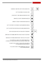
Page 9: ...NER TS10 8 4 INSTRUCTIONS FOR USE 4 1 Panel description Picture 6 Control panel of the Welding Positioner Potenciometer to regulate turning speed Emergency button Information display LED S light pilot...

Page 10: ...EMORIES MENU KEY TO ACCEDE THE DISCONTINOUS WELDING MEMORY MENU KEYS FUNCTION DIN JUST FOR THE USE OF THE ROBOT INDICATES THE TURNING DIRECTION OF THE PLATE TO THE RIGHT INDICATES THE TURNING DIRECTIO...

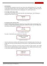
Page 11: ...d properly please press the ESC key Then and just in case you finish feeding up the machine as it has been described before it will appear an initialization message in the LCD display while the machin...

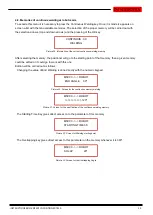
Page 12: ...press OK Picture 11 Information of the current continuous welding memory After selecting the memory the weld positioner will place in the starting point of this memory At this moment either a given me...

Page 13: ...welding starts following the parameters of it and in the specified Picture 18 Screen for Continuous welding memory Once the welding sequence is finished the weld positioner will go back again to the W...

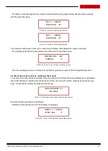
Page 14: ...ure 20 Screen for discontinuous welding memory Picture 21 Screen of Discontinuous welding memory Length od welding Picture 22 Screen of the discontinuous welding memory Gap between welding Picture 23...

Page 15: ...ter welding robot In this case the manual performance is cancelled However the discontinuous and continuous welding memories keep on performing exactly like in the Positioner Mode The only difference...

Page 16: ...ation of the current continuous welding memory After selecting the memory the positioner will go to the starting point of that memory then a given memory could be edited or it could go to work with th...

Page 17: ...parameters of this with the specified sense Picture 36 Screen of the continuous welding memory Once the welding sequence is finished the positioner goes back again to the Welding Starting Point 4 9 Me...

Page 18: ...lding memory Welding length Picture 40 Screen of the discontinuous welding memory Gap between welding Picture 41 Screen of the discontinuous welding memory To accede the turning direction parameters s...

Page 19: ...al and then let it loose after having introduced the piece to be worked the indicated welding cycle begins Picture 46 Screen of Pantalla de Memoria de soldadura discontinua When a welding operation en...

Page 20: ...but the ones described in this manual Wear safety googles and boots according to the EC regulations Keep a safety distance between the machine and the operative during the time the machine is perform...

Page 21: ...Technical annex Weld Positioner TS10 List of parts Electrical map Electric box connections Electronic plate...

Page 22: ...INSTRUCTIONS BOOK OF WELD POSITIONER TS10 A 2 A1 List of parts...

Page 23: ...INSTRUCTIONS BOOK OF WELD POSITIONER TS10 A 3...

Page 24: ...INSTRUCTIONS BOOK OF WELD POSITIONER TS10 A 4 A2 Electrical map...

Page 25: ...INSTRUCTIONS BOOK OF WELD POSITIONER TS10 A 5 A3 Electric box connections...

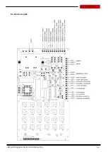
Page 26: ...INSTRUCTIONS BOOK OF WELD POSITIONER TS10 A 6 A4 Electronic plate...

Page 27: ...ty has been extended up to three years WARRANTY REGISTRATION 1 Among www nargesa com on our site 2 Select the menu Warranty Registration 3 Complete the form with your details and press 4 Message Sent...

Reviews: