7
CONNECT THE CAMERAS
Install the analog video cameras and run the camera coaxial cable to the Video Gateway. Connect the camera ca-
bles to the BNC video-in ports of VIP-Gateway.
CONNECT THE VIP-GATEWAY TO ROUTER
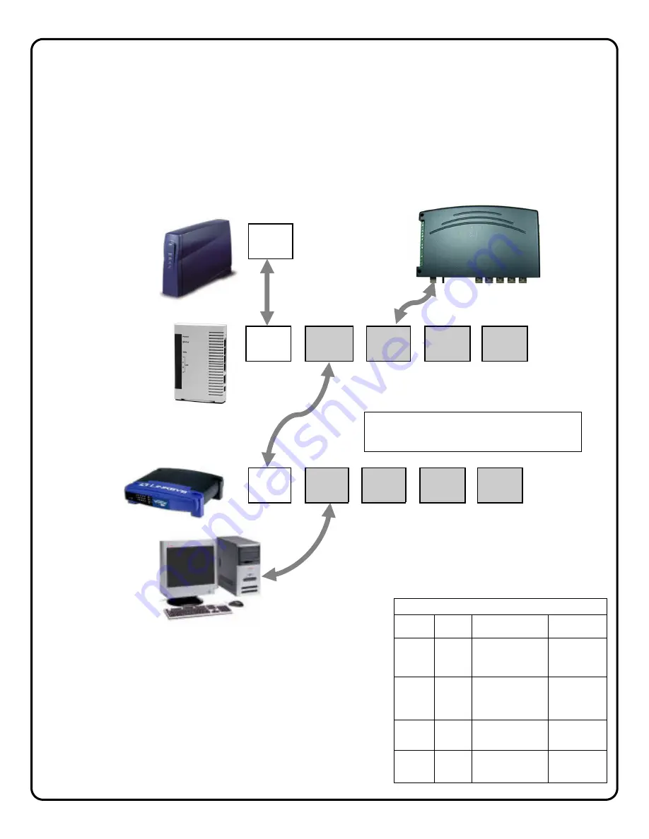
1. Power-down existing network devices (i.e. Cable Modem, Router, etc.).
2. Connect the Cable or DSL Modem to the G-Box WAN port.
3. Connect VIP-Gateway to any G-Box LAN port.
4. If necessary, you may connect existing PC to any available LAN port --OR--if customer has a router, connect the
router WAN port to any available LAN port.
5. Power Up all the devices. Several minutes may be required for the
DHCP sessions to take place.
6. Record the VIP-Gateway Mac Address (bottom label, example:
0009B5106763) which will be needed in the subsequent registration
steps:
Go to VIP-Gateway Configuration page 8.
Indicator
Color
Solid
Flashing
Power
Green
Turns solid green
when power is
applied to device.
N/A.
Status
Red
Turns solid red
when the device is
not working prop-
erly.
WAN
Green Connected
and
linked to a Cable/
DSL Modem.
Receiving/
Sending data
LAN 1
to
LAN 4
Green
Turns green when
linked to a local
network.
Receiving/
Sending data
G-BOX LED INDICATORS
BROADBAND
MODEM
G-BOX
WAN
CUSTOMER’S
ROUTER
CUSTOMER’S
PC
If no router installed, connect PC
directly to the G-BOX LAN ports
WAN
LAN1
LAN2
LAN3
LAN4
Note:
G-BOX LAN Ports are auto-sensing. Customer’s devices or
VIP-Gateways may be plugged into any port
.
WAN
LAN1
LAN2
LAN3
LAN4
VIP-GATEWAY


