background image


15 

SETTING UP THE EOP MODULES  


Setup 

Connect the CAT5 cable from an EOP module to the gateway and plug into AC wall socket.


Connect the CAT5 cable from an EOP module to the G-BOX and plug into  AC wall socket.


Wait a minute for startup to be completed, and then check the LED's. 


• The 

Power 

LED should be ON. 

• The 

PLC Link 

LED will be ON if the other EOP modules are detected, otherwise it will be OFF. 

• The 

Ethernet 

LED should be ON. 

 
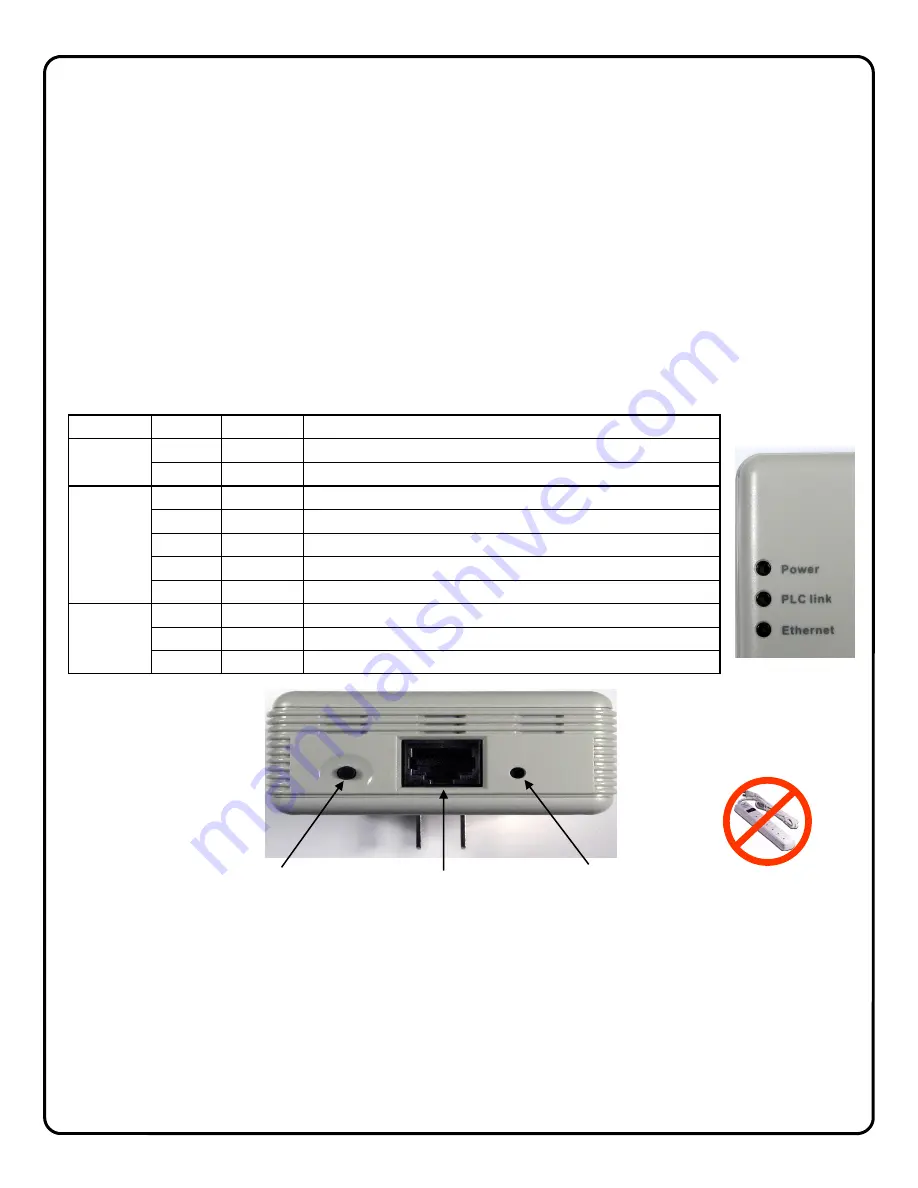
Controls and Indicators 


Security Button 

 Press 

the 

Security Button 

to activate the AES encryption and create a secure network. 

 Please 

refer 

to 

Creating a secure EOP network 

section for more details. 

 
LAN Port  

  Connect the device to the EOP module using provided RJ45 terminated CAT5 cable. 


Reset Button 

  Press and hold the 

Reset Button 

to clear all data and restore settings to the factory 

default values. 

LED


COLOR


STATE


STATUS


Power


Off


No power


Blue


On


Normal operation


PLC link


Blue


On


EOP network active - at least one other device detected


Blue


Flashing


Data receive rate greater than 80Mbps


Pink


Flashing


Data receive rate between 50 Mbps and 80Mbps


Red


Flashing


Data receive rate less than 50 Mbps


Off


EOP network not available - no other devices detected


Ethernet


Off


No Ethernet connection detected


Blue


On


Ethernet connection is active


Blue


Flashing


Data is being transmitted or received via the Ethernet Port


The ISEE-EOP MOD200 has three LED indicators that display the EOP status. 
 

SECURITY 

BUTTON 

LAN 

PORT 

RESET 

BUTTON 

Note: If AC power-strips 
are required due to un-
available AC outlets, non 
surge protected or noise 
filtered power-strips must 
be used.  Many AC power-
strips utilize internal surge 
protection that may pre-
vent the EOP modules 
from operating.   

EOP module must 

be plugged directly 

into wall outlet 

Summary of Contents for iSeeVideo ISEE-SCHGW

Page 1: ...New York 11701 For Sales and Repairs 800 645 9445 For Technical Service 800 645 9440 Publicly traded on NASDAQ Symbol NSSC NAPCO 2009 Designed exclusively for use with NAPCO iSeeVideo VideoAlert net...

Page 2: ...rt net service SCHGW EOP 12 Additional Gateway Kit Includes 1 ISEE SCHGW Power Adapter 1 ISEE EOP MOD200 6 CAT5 cable 12 months VideoAlert net service ISEE SCHGW 12 Single Channel Gateway Includes 1 I...

Page 3: ...The modules create a powerline network ideal for the transmission of video signals at up to 200 megabits per second The EOP modules are fully capable of transmitting data across the phases of typical...

Page 4: ...on page 6 3 Activate the new ISEE SCHGW account on the VideoAlert server page 7 4 Configure the gateway for motion detection triggering Optional Page 12 Optional The gateway may be configured for moti...

Page 5: ...indicate that video device is being accessed viewed POWER Lights to indicate that module power is present ETHERNET Connect CAT5 cable from broadband modem or network to RJ 45 terminal POWER Connect t...

Page 6: ...ntify the type of ISP or identify the modem or routers that may be in front of the internet connection provided by the subscriber In these cases wire as shown below 1 Connect the VIP devices directly...

Page 7: ...s gateway and enter the Subscriber details see below ADD or REPLACE a VIP Device To add or replace a gateway to the account click here See Adding additional gateways to an existing account for more de...

Page 8: ...firmation section verifies all information en tered above Be sure to check the accuracy of the information dis played and if changes are required click the Prev but ton to edit any previously entered...

Page 9: ...iewer should always be enabled Click Update to add the new user and return to the previous screen or click Prev to cancel and return to the previous screen The system supports a maximum of 5 Users inc...

Page 10: ...added S C _ _ _ _ _ _ Click Next 2 The Dealer Branding screen will appear Enter your Company Dealer Admin ID and Password and click Next 3 After Dealer Branding is complete click Add or Replace a VIP...

Page 11: ...continue 5 The following screen allows the entry of the gateway description in the Enter New Device Description field Click the pull down menu and select Add De vice to complete the addition of the n...

Page 12: ...en activated the ISEE SCHGW may be configured The next several pages will guide you through the on line configuration process Note If the ISEE SCHGW is only to be used for live viewing and there are n...

Page 13: ...deo captured before the actual sensing of motion and the Post Capture Length being the length of the video after the sensing of motion Use the slider control for each respective Area box to adjust the...

Page 14: ...nal Note Prior to using the audio feature it is recom mended that the viewer listener obtain any required advance consent of the occupants of the premises HW Trigger Input Select to enable the normall...

Page 15: ...data and restore settings to the factory default values LED COLOR STATE STATUS Power Off No power Blue On Normal operation PLC link Blue On EOP network active at least one other device detected Blue...

Page 16: ...3 seconds EOP Power LED flashes 2 Hold down the SECURITY button on other EOP module for 3 seconds EOP Power LED flashes 3 After a few seconds the Power and PLC link LED s should be on The configuratio...

Page 17: ...pening of a protected door disarming of the system etc 6 I have a wireless router connected to my broadband modem How can I keep my network settings after the G BOX is installed Upon installation the...

Page 18: ...self by a unique ID to the server to update the IP address Static IP Address An IP address whose value does not change DHCP Dynamic Host Configuration Protocol a protocol for assigning dynamic IP addr...

Page 19: ...19 NOTES...

Page 20: ...purporting to act on its behalf to modify to change or to assume for it any other warranty or liability concerning its products In no event shall NAPCO be liable for an amount in excess of NAPCO s or...

Reviews: