14 Gemini C-Series GEMC-NAC Extender Installation Instructions
MOUNTING AND INSTALLATION
2. INSTALL THE GEMC-24VR CIRCUIT BOARD
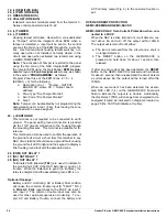
GEMC-24VR BOARD (ASSEMBLED VIEW)
SEE TABLE BELOW FOR NUMBER DESCRIPTIONS
Item
Part No.
Description
Quantity
1
H448
Enclosure base
1
2
N101
6-32 kep nut
4
3
SO216
Spacer, 1/4" x .313, 6-32 tapped
4
4
PCB Boost Bus Circuit
PCB
1
5
SC631
Screw, 6-32 x 7/8 pph
4
6
HW1489
Battery Shelf
1
GEMC-24VR BOARD (EXPLODED VIEW)
SEE TABLE BELOW FOR NUMBER DESCRIPTIONS
5
6
3
4
2
1
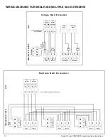
1. ROUTE CONTINUOUSLY POWERED 120VAC
If not already installed, mount a separate electrical gang box
(single or double gang) located no closer than 6 inches and
no further than 12 inches from the upper left side of the
eventual mounting location of the control panel enclosure.
A continuously-powered (un-switched) 120VAC source with
a maximum 15A dedicated branch circuit with grounding
conductor must be wired into this gang box by a licensed
electrician in accordance with all national and local electrical
codes.
ELECTRICAL
GANG BOX
Distance between gang box
and panel enclosure must be
between 6 and 12 inches.
CONTROL PANEL
ENCLOSURE
6" - 12"
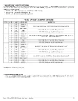
into the SO216 Spacers (item 3) as shown.
2. Place the GEMC-24VR PC Board on top of the
SO216 Spacers and secure with the 6-32 kep nuts
(item 2) as shown. Do not over-tighten nuts.
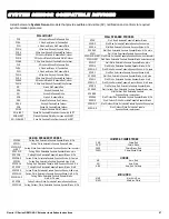
The GEMC-24VR allows one of the four NAC outputs to be
a "regulated" 24V output supplying a constant voltage to
Listed 24V Accessories as per the UL Standard for Safety
for Control Units and Accessories for Fire Alarm Systems
(UL 864). Secure the GEMC-24VR printed circuit board to
the HW1489 battery "Shelf" as follows:
1. Insert four SC631 screws (item 5) such that the
threads protrude from the bottom of the HW1489
battery Shelf (item 6) as shown. Secure the screws
The images below show the installation instructions for the smaller enclosure (model GEMC-NAC7S); the larger enclosure
diagrams are similar, except the larger enclosure (model GEMC-NAC7L) includes an additional battery shelf and tamper
switches.


