44
S06
STARTING & RUNNING
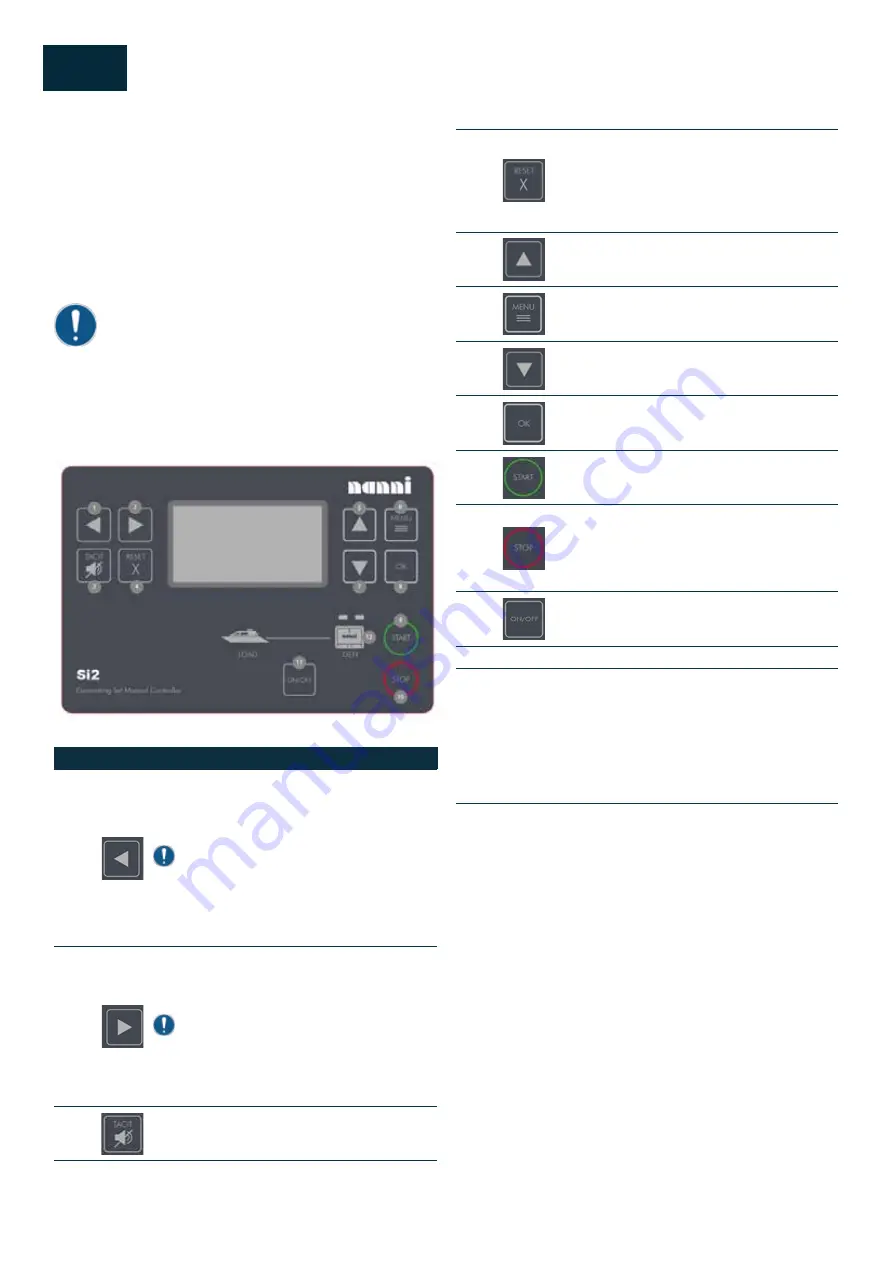
COMMAND PANEL SI-2
This panel integrates all the information necessary for the
operation and monitoring of the generator set. The control
panel is delivered complete in working condition and does
not require any internal wiring by the user. The connection
to the generator engine is made via a dedicated extension
cable or installed on the sound Proof.
IMPORTANT!
The control panel must be integrated in a dash protected
from splashing water.
DESCRIPTION OF THE GENERATOR SET
CONTROL PANEL
Pos.
Pic.
Description
1
LEFT button.
Use this button to move left or
to change the mode. The button can change
the mode only if the main screen with the indi-
cator of currently selected mode is displayed.
Note!:
This button will not change the mode if the
controller mode is forced by one of binary in-
puts listed in the Reference Guide – “Operat-
ing modes” chapter.
2
RIGHT button.
Use this button to move right or
to change the mode. The button can change
the mode only if the main screen with the indi-
cator of currently selected mode is displayed.
Note!:
This button will not change the mode if the
controller mode is forced by one of binary in-
puts listed in the Reference Guide – “Operat-
ing modes” chapter.
3
HORN RESET button.
Use this button to deac-
tivate the horn output without acknowledging
the alarms.
4
FAULT RESET button
. Use this button to ac-
knowledge alarms and deactivate the horn
output. Inactive alarms will disappear im-
mediately and status of active alarms will be
changed to “confirmed” so they will disappear
as soon as their reasons dismiss.
5
UP button
. Use this button to move up or in-
crease value.
6
PAGE button.
Use this button to switch over
display pages.
7
DOWN button
. Use this button to move down
or decrease value.
8
ENTER button.
Use this button to finish editing
a set-point or moving right in the history page
9
START button.
Works in MAN mode only.
Press this button to initiate the start sequence
of the engine.
10
STOP button.
Works in MAN mode only. Press
this button to initiate the stop sequence of
the Gen-set. Repeated pressing of button will
cancel current phase of stop sequence (like
cooling) and next phase will continue.
11
GCB button.
Works in MAN mode only. Press
this button to open or close the GCB.
Indicators and others
12
GENERATOR status indicator.
There are two states –
Gen-set OK (indicator is green) and Gen-set failure
(indicator is red). Green LED is on if the generator volt-
age and frequency is present and within limits. Red
LED starts flashing when Gen-set failure occurs. Af-
ter FAULT RESET button is pressed, Red LED goes to
steady light (if an alarm is still active) or is off (if no
alarm is active).
Summary of Contents for Q1100 Series
Page 1: ...NANNI GENERATOR SET USER MANUAL DGBXXT090048 Q1100 Series...
Page 2: ......
Page 4: ...4 Q00 TRACKED CHANGES...
Page 8: ...8 S00 SUMMARY...
Page 32: ...32 S03 FLUIDS...
Page 38: ...38 S05 COMPOSANTS...
Page 40: ...40 S05 COMPOSANTS VIEW N 1 OF THE GENERATOR SET...
Page 41: ...41 S05 COMPOSANTS VIEW N 2 OF THE GENERATOR SET...
Page 52: ...52 S 07 MAINTENANCE Battery voltage 72 Battery specific gravity 72...
Page 53: ...53 S 07 MAINTENANCE...
Page 74: ...74 S 07 MAINTENANCE...
Page 76: ...76 S08 AL TERNATOR...
Page 88: ......
Page 96: ...96 S11 TROUBLE SHOOTING...
Page 97: ......
Page 98: ......


