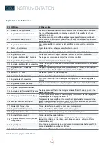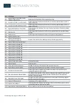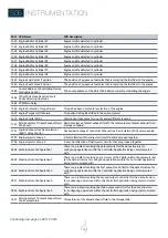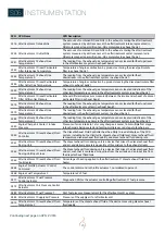
40
S06
INSTRUMENTATION
DISPLAYED DATA
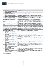
After powering, and after SI.3 booting, the normal se-
quence displays engine function parameters such as :
Engine Rotary peer minutes : xxxx Tr/min or RPM
Engine Oil pressure : xx Bar
Engine Température : xxx °C
Engine Battery Voltage: xx V
Engine hours : xxx hrs
Engine Load : xxx %
Throttle position. xxx %
Engine Fuel Rate: xxx L/min
Engine Boost pressure : xx kPa
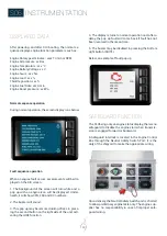
Normal sequence operation
During normal operation, the screen display is as below:
Fault sequence operation
When an engine fault occurs, several events will be dis-
played on the SI3 screen.
1. The background of the screen will turn white and a
pop up with an engine icon will be displayed. Under-
neath, it will show SPN, FMI and OC numbers.
2. The buzzer will sound.
3. This pop up may be removed during 20 sec in press-
ing the second button on the right side of the unit, acti-
vating the HIDE function.
4. The display returns to normal operation and, after a
delay, the pop up fault will come back if fault has not
been resolved in the mean time.
5. The buzzer may be disabled in pressing the bottom
right button (MUTE).
Below, an example of fault pop up :
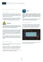
SAFEGUARD FUNCTION
The SI.3 being only an engine status display, there is no
safeguard to disable the engine start when transmis-
sion is engaged forward or backward.
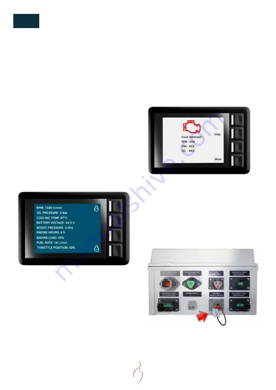
A Safeguard interlock is located in the Engine Control
Box through the Neutral Safety Switch Port. It is the
duty of the shipyard to make the appropriate wiring.
Upon delivery, the Neutral Safety Switch port is shorted
to allow preliminary engine tests only. The engine sup-
plier has no responsability in case of improper safe-
guard wiring.
Summary of Contents for N16.1000 CR3
Page 2: ......
Page 4: ......
Page 34: ...34 S05 COMPONENTS ENGINE VIEWS N16 CR3...
Page 35: ...35 NOTES...
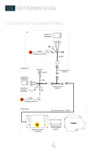
Page 48: ...48 S06 INSTRUMENTATION SYSTEM LAYOUT INCLUDING OPTIONS...
Page 118: ......

