31
7. OPERATION
7-4-6 Input test (INPUT TEST)
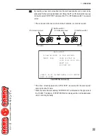
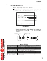
This screen is used to test the switches such as the buttons on the control panel.
Select “INPUT TEST” on the test mode menu screen (see page 25), and press the
P1 Button switch 1. The Input Test screen appears.
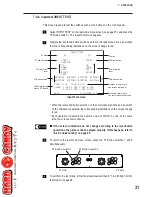
Operate the levers and button switches on the control panel one by one, and check
that the corresponding indications on the screen change to red.
* When the levers and button switches on the control panel and the service switch
on the cabinet are operated, the corresponding indications on the screen change
to red.
* Each operation increments the numeric value of COIN 1 by one. At the same
time, the coin counter counts up.
z
z
z
z
z
If the screen indications do not change according to the lever/button
operations, the game cannot be played properly. If this happens, refer to
“8-2 Troubleshooting” on page 46.
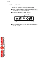
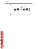
To return to the test mode menu screen, press the P1 Button switches 1 and 2
simultaneously.
P1 Button switch 1
P1 Button switch 2
P1 side
P2 side
To exit from the test mode, follow the procedure described in “7-4-2 Exiting from the
test mode” on page 26.
P1 Start switch
P1 8-direction
lever
DIP switches on
Game PC Board
P2 Start switch
P2 side
P1 side
P2 8-direction
lever
P2 Button switch
Method of returning to
the test mode menu screen
P1 Button switch
Number of coin switch
operations (default: 0)
INPUT TEST
P1
START
SERVICE
UP
DOWN
LEFT
RIGHT
TEST
BUTTON1 BUTTON2
BUTTON3 BUTTON4
P2
START
UP
DOWN
LEFT
RIGHT
BUTTON1 BUTTON2
BUTTON3 BUTTON4
COIN 1:000 COIN 2:000
DIPSW 1:OFF 2:OFF 3:OFF 4:OFF
5:OFF 6:OFF 7:OFF 8:OFF
EXIT: P1-BUTTON 1&2
...
...
...
...
Input Test screen

