


Page 4 of 14
4/21 IOM-MAC-700-INST
Nailor Industries Inc. reserves the right to change any information concerning product or specification without notice or obligation.
Dimensions are in inches (mm).
INSTALLATION INSTRUCTIONS FOR THE MAC-700
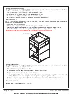
The MAC-700 is fully assembled from the factory except for the UV lights and the door key which are shipped separately.
Step 1
Carefully remove the unit from the shipping carton and inspect for damage that may have occurred during shipping. If
shipping damage is found, do not install. Call Nailor customer service to report damage.
Step 2
Wipe down the unit to remove shipping dust and debris.
Step 3
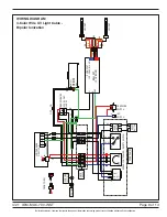
Plug into the wall outlet. The MAC-700 unit is furnished with a 120 V plug for utilizing in a standard wall outlet. A
qualified person should wire the unit to the appropriate power supply and install the UV lights. Refer to the wiring
diagram on page 9 or 10.
PRODUCT OVERVIEW
The MAC-700 provides continuous filtration of the space air to help reduce the risk of biological aerosol transmission without
the requirement to involve your existing HVAC system. The MAC-700 is designed to pull air from all sides to increase its ability
to collect biomass and dust from the floor. The air will travel through a MERV 10 pre-filter, which captures large particles, HEPA
filter and UV-C light before recirculating purified near sterile air up into the room. The final 6" (152 mm) HEPA filter provides
filtration that is 99.99% effective in the removal of microbial content from the airflow.
AIR FLOW ADJUSTMENT
The MAC-700 contains a highly efficient ECM motor and forward inclined fan. Airflow can be
easily adjusted through a 0 - 10 speed controller on the back of the unit. To increase the airflow
simply turn the speed controller knob clockwise from 0 to 10. At 10, the maximum 700 CFM will
be achieved.
Figure 1. Speed Controller
Dial to CFM
10
700
9
630
8
570
7
520
6
475
5
415
4
360
3
280
2
140
1
80
Dial To Airflow Guidance
27" (686)
51"
(1295)
DOUBLE
DEFLECTION
GRILLE
HEPA
FILTER
SAFETY
SWITCH
LOCATED
INSIDE OF
DOOR
EC MOTOR
UV-C LIGHT
UV-C LIGHT
MERV 10
PRE-FILTER
HOUR METER
RESET BUTTON
LFI
PRESSURE
SWITCH
ELECTRICAL
BOX
EGGCRATE
GRILLE
CASTORS (4)
DOOR
LATCHES
2 1/8" (54)
SPEED
CONTROLLER
LOADED
FILTER
INDICATOR
ILLUMINATED
ON/OFF
BUTTON
0.0
HOURS
UV-C HOUR METER
5
0
1
9
3
7
2
8
10
4
6
UV-C
HOUR
COUNTER
0.0
HOURS
UV-C HOUR METER
5
0
1
9
3
7
2
8
10
4
6


