background image

GB

NAD

4

NAD 613 CASSETTE DECK

INSTALLATION

The recorder may be installed on any stable sur-

face that is not subjected to vibration or intense mag-
netic fields. It should not be placed directly on a loud-
speaker, a television set, or a large power amplifier
where it might pick up hum from the amplifier’s power
transformer. if you wish to install the recorder next to
an amplifier on the same shelf, place the recorder on
the left so that its cassette compartment will be locat-
ed away from the amplifier.

WARNING TO UK USERS. If this appartus is not fit-
ted with a UK three-pin plug, do not attempt to insert
the attached plug into a UK mains socket. Instead, cut
the plug from the mains lead and attach a fused UK
three-pin plug using the following safety advice on
wiring.
IMPORTANT. The wires in this mains lead are
coloured BLUE and BROWN;
BLUE: NEUTRAL

BROWN: LIVE

The colours of these mains lead wires may not corre-
spond with the coloured markings identifying the ter-
minals in your plug. In this case the BROWN wire
must be connected to the terminal which is marked
L(ive) or coloured RED. The BLUE wire must be con-
nected to the terminal marked N(eutral) or coloured
BLACK. No connection should be made to the termi-
nal marked E or coloured green or green and yellow 

PRECAUTIONS

To ensure that maximum performance of the NAD

613 cassette deck is maintained over time, please
bear the following precautions in mind:

THE DECK

A. Make sure the heads and transport are cleaned
regularly.  Please refer to page  8.
B. Demagnetise both heads and tape guidance from
time to time. Please refer to page 8.
C. The bearings and other moving parts have been
treated with special lubricants and are therefore main-
tenance-free. Additional lubrication can actually cause
malfunctioning.
D. Do not position the deck near equipment with
strong magnetic fields, such as loudspeakers or tele-
visions, etc.
E. Place the deck on a solid, flat surface.
F. Avoid dirt, dust, sand, etc. from entering the deck.
G. Avoid placing near transmitters: they can generate
high frequencies which may cause malfunctioning of
the deck. 
H. Ensure the cassette deck compartment lid is
closed when the deck is not in use. Open it only for
taking a cassette in or out, or for cleaning the heads
and tape guides.
I. Do not place the deck directly on top of a (power)
amplifier or receiver. The deck may pick up hum from
the amplifier’s power transformer. Some amplifiers
can also generate a fair amount of heat, even when
on stand-by.

WARNING : BEFORE PLUGGING IN THE UNIT FOR
THE FIRST TIME, READ THE FOLLOWING SECTION
CAREFULLY.

Some models are designed for use only with the

power supply voltage of the region where they are
sold. 

European models:

AC 230V, 50Hz

U.S.A. and Canadian models: 

AC 120V, 60Hz

THE CASSETTE TAPES

A. Store the cassette tapes in their jewel case, away
from dust. Never store tapes in direct sunlight or very
hot places.
B. Always use cassette tapes of a good quality.
Besides mediocre results, poor quality tapes can
cause excessive head wear.
C. Never touch the exposed tape itself or take it out of
its cassette casing.
D. In most cases the cassette tape has a five to eight
second leader tape at both the beginning and end of
a cassette tape. As you cannot record on this leader
tape, be sure to commence recording beyond this
tape.

REAR PANEL CONNECTIONS &
CONTROLS.

The numbers in the text refer to the connections in

figure “REAR PANEL CONNECTIONS”

This cassette deck can be connected to almost all

pre-amplifiers, integrated amplifiers or receivers.
Ensure the plugs are fully inserted and the recording
and playback cables are connected properly.

1. INPUT.

Connect a cable from the deck’s “LINE IN” jacks at

the rear panel to the TAPE OUT or REC jacks of your
amplifier. Connect the left channel of the deck to the
left channel of the amplifier and connect the right
channel of the deck to the right channel of the amplifi-
er. Normally, the red plug is used for the right chan-
nel, the black or white plug for the left channel.
Please refer to figure 1.

2. OUTPUT.

Connect a cable from the deck’s “LINE OUT” jacks

at the rear panel to the TAPE IN, PLAY, or MONITOR
jacks of your amplifier. Connect the left channel of the
deck to the left channel of the amplifier and connect
the right channel of the deck to the right channel of
the amplifier. Normally, the red plug is used for the
right channel, the black or white plug for the left chan-
nel. Please refer to figure 1.

3. NAD LINK.

The “NAD Link IN” connector allows the NAD 613

to be operated by external remote control signals
passed from another NAD remote control component
featuring NAD Link, e.g. AV 716 receiver. NAD Link
works in a “daisy chain” fashion, connections going
from one unit to the next one. Many NAD receivers
and AV components come supplied as standard with
an NAD system remote control which sports buttons
for most used tape transport functions (Play, Record,
Fast Forward, Rewind, Stop, etc.). It is recommened
that the NAD 613 is the second unit in the daisy chain
after the “master” unit, usually a receiver. Connect a
cable from the master unit Link Out (e.g. the AV 716)
to the NAD Link IN jack on the 613. 

Summary of Contents for 613

Page 1: ...GB F D E I P S NAD 613 OWNER S MANUAL MANUEL D INSTALLATION BEDIENUNGSANLEITUNG MANUAL DEL USUARIO MANUALE DELLE ISTRUZIONI BRUKSANVISNING MANUAL DO PROPRIET RIO 1995 NAD ELECTRONICS LTD 613...

Page 2: ...to the point of cable entry as practical NAD 2 CAUTION RISK OF ELECTRIC SHOCK DO NOT OPEN ATTENTION RISQUE DE CHOC ELECTRIQUE NE PAS OUVRIR CAUTION TO REDUCE THE RISK OF ELECTRIC SHOCK DO NOT REMOVE...

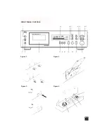
Page 3: ...NAD 3 FRONT PANEL CONTROLS Figure 1 Figure 2 Figure 3 Figure 4 1995 NAD ELECTRONICS LTD 613...

Page 4: ...en when on stand by WARNING BEFORE PLUGGING IN THE UNIT FOR THE FIRST TIME READ THE FOLLOWING SECTION CAREFULLY Some models are designed for use only with the power supply voltage of the region where...

Page 5: ...the POWER 1 switch After use the unit can be switched off by pressing the button again Press the OPEN 3 button to release the cas sette compartment door and insert the tape with the thick edge where...

Page 6: ...ut Refer to chapter How to get the best performance from your NAD 613 cas sette deck section Recording level for more detailed information 13 BALANCE The recording balance between left and right chan...

Page 7: ...ls dolby HX Pro is a system that compensates for these undesirable fluctuations dur ing recording It does not operate during playback so cassettes recorded with Dolby HX Pro can be played back on deck...

Page 8: ...sound Play Trim is a special high frequency play back equalisation circuit used to restore accurate play back response before Dolby NR decoding takes place Standard play back equalisation for correct...

Page 9: ...plificateurs produisent aussi une quantit assez importante de chaleur m me en tat de veille LES BANDES A CASSETTE A Stocker les cassettes dans leur tui l abri de la poussi re Ne jamais stocker les cas...

Page 10: ...i les modes Pause enregistrement et Pause lecture 6 PLAY LECTURE Appuyer sur ce bouton pour lire une cassette L ic ne de lecture s allume sur l affichage Pour charger une bande cassette la retirer de...

Page 11: ...sur le bouton d ENREG ISTREMENT RECORD 10 et sur le bouton de PAUSE 7 Le t moin rouge d Enregistrement Record et l ic ne de Pause s allument sur l affichage R gler le niveau d enregistrement l aide de...

Page 12: ...arr te de clignoter et s allume en permanence jusqu ce que la section pr s lec tionn e ait t r p t e cinq fois ou jusqu ce que l on appuie sur le bouton d ARRET STOP 17 DOLBY NR Les syst mes DOLBY NR...

Page 13: ...qu 0000 environ 7 Ecouter l chantillon de musique et valuer son quilibre total par rapport l original 8 Si l enregistrement donne une sonorit plus mouss e que l original baisser le niveau de la Correc...

Page 14: ...t diminuer le r glage du bouton Alignement de Lecture Play Trim sens anti horaire pour obtenir des aigus plus lisses NOTA La commande Alignement de Lecture Play Trim n affecte que la lecture Elle ne f...

Page 15: ...r auf einen Leistungs Verst rker oder Receiver stellen Der Recorder kann u U ein Netzsummen von dem Stromtransformator des Verst rkers aufnehmen Einige Verst rker erzeugen au erdem betr chtliche W rme...

Page 16: ...e Aufnahme Schnellvorlauf und R ckspulen unter brochen Auch der Aufnahme und der Wiedergabepausebetrieb werden mit dieser Taste ausgeschaltet 6 PLAY Wiedergabe ber diese Taste die Wiedergabe eines Cas...

Page 17: ...en jedoch aktiv Wenn Sie mit der Aufnahme fortfahren m chten die Taste PLAY 6 dr cken Diese Einrichtung ist bei Aufnahmen von Radio bzw Fernsehsendungen n tzlich um Ansagen oder Werbespots von der Auf...

Page 18: ...diese Hochfrequenzsignale ber 15kHz Bei solchen Problemen die Taste MPX dr cken In der Anzeige leuchtet MPX FILTER Wenn Sie keine Radiosendungen aufnehmen ist Anwahl des MPX Filters nicht erforderlic...

Page 19: ...n berm iges Bandrauschen zur Folge w hrend zu hohe Aufnahmepegel zu Verzerrungen f hren Normalerweise wird der Aufnahmepegel auf den lautesten Teil der Musik eingestellt und dann werden keine weiteren...

Page 20: ...fe A B und die Bandantriebsrolle C mit einem Wattest bchen mit reinem Alkohol oder mit einem speziellen Cassettenrecorder Reiniger reini gen Die Klemmrolle D nur mit distilliertem Wasser reinigen Niem...

Page 21: ...ette en su estuche alejadas del polvo No guarde cintas jam s en lugares que est n bajo la luz directa del sol o que est n muy calientes B Use siempre cintas de cassette de buena cali dad Aparte de los...

Page 22: ...r una cinta de cassette qu tela de su estuche Antes de insertar la cassette asegure que la cinta est enderezada y tensa en la parte en que est expuesta en el borde grueso de la cassette N B Si es nece...

Page 23: ...n a 0000 despu s de que se desconecta la alimentaci n el ctrica 12 RECORD LEVEL NIVEL DE GRABACION El nivel de grabaci n para los dos canales puede controlarse con este control Las 2 barras horizon ta...

Page 24: ...ipos de reduc ci n de ruido Dolby NR Dolby C NR provee el mayor silenciamiento del ruido sibilante de la cinta lo que es importante cuando se graban actuaciones musi cales en directo o grabaciones con...

Page 25: ...l detente central de su gama grabando cada canal con niveles iguales Si desea borrar una cinta sin hacer una nueva grabaci n siga el procedimiento descrito antes pero gire el control RECORD LEVEL 12 t...

Page 26: ...n la cinta se magnetizan un poco con el tiempo Este magnetismo aumenta el ruido sibilante tanto durante la escucha como durante la grabaci n Por lo tanto es aconsejable desmagnetizar los cabezales rod...

Page 27: ...anche se sono in condizione di attesa stand by LE CASSETTE A Conservare le cassette nell apposito portacas sette e sempre in luogo non impolverato Non conser vare mai cassette esposte direttamente ai...

Page 28: ...cendere l unit premendo l interruttore POWER 1 Dopo l uso l unit pu essere spenta premendo una seconda volta questo pulsante Per aprire lo sportellino del portacassette pre mere il pulsante OPEN 3 ed...

Page 29: ...E Il livello di registrazione per entrambi i canali pu essere regolato tramite questo comando Le due lineette orizzontali sul display danno un indicazione precisa del livello di registrazione durante...

Page 30: ...iduzione dei disturbi Il Dolby C NR fornisce l affievolimento massimo del sibilo del nastro impor tante durante la registrazione dal vivo o per la regis trazione con larga gamma dinamica ad esempio co...

Page 31: ...senso completamente antiorario Non si ha l accensione di alcun segmento per il livello di regis trazione PREVENZIONE DELLA CANCELLAZIONE ACCIDENTALE Mentre si effettua una nuova registrazione quelle p...

Page 32: ...sibilo sia durante l ascolto sia durante la registrazione Pertanto si raccomanda si smagnetiz zare le testine il rullino e le altre parti metalliche di guida impiegando uno smagnetizzatore o una cass...

Page 33: ...id sj lva bandet med fingrarna Fett och smuts fr n fingrarna kan d smetas av p tonhu vudena D I de flesta fall har kassetband ungef r fem till tta sekunders blanktape i b rjan av bandet Se till att du...

Page 34: ...terst lla diskanten Om bandet ist llet l ter vasst och p tr ngande vrid PLAY TRIM motsols f r en mjukare och behagligare diskant F r mer information om PLAY TRIM se i sty cket Hur du f r ut det mesta...

Page 35: ...16 REPEAT NAD 613 r utrustad med tv olika typer av repetering repetering av en hel bandsida eller ett valt avsnitt fem g nger Repetitionsknappen kan tryckas f r tre olika l gen som visas i f nstret O...

Page 36: ...f r stark signal andra sidan f r sig nalen inte vara s svag att musiken dr nks i band brus Bandtillverkarna brukar ange hur stark signal ban det klarar p kassettfodralet Bandspelaren k nner sj lv av v...

Page 37: ...ar som visas i figur 4 AVMAGNETISERING De delar som har direktkontakt med bandet blir n got magnetiska med tiden Magnetismen ger ett kat brus vid b de in och avspelning Vi rekom menderar d rf r att me...

Page 38: ...e calor mesmo quando est o de reser va FITAS DA CASSETE A Guarde as fitas da cassete no respectivo estojo longe de poeira Nunca guarde fitas expostas luz directa do sol ou em lugares muito quentes B U...

Page 39: ...cada onde fica exposta no rebordo espesso da cassete N B Se for necess rio coloque um l pis em qual quer dos cubos e enrole manualmente o carretel da fita at ser tomada qualquer folga Ligue a unidade...

Page 40: ...ot o STOP PARAGEM 5 Nota A redu o da reprodu o n o tem efeito durante a grava o 11 RESET REAJUSTE Prima este bot o para reajustar o contador da fita para 0000 O contador pode ser reajustado em qualque...

Page 41: ...ando a grava o reproduzida O filtro MPX bloqueia estas altas frequ ncias superiores a 15kHz Prima o bot o MPX se estiver a sofrer estes prob lemas o FILTRO MPX ir acender se no ecr Se n o estiver a fa...

Page 42: ...spectivas regu la es em rela o a este tipo de fita Um n vel de grava o baixo demais resultar num sibilar excessi vo da fita enquanto que um n vel de grava o alto demais resultar em distor o O m todo p...

Page 43: ...sete No fundo do compartimento encontrar as cabe as e as guias da fita cabrestante e rolo de recolha Consulte a figura 3 Limpe as cabe as A e B e o cabrestante C usando peda os de algod o em rama hume...

Page 44: ...annel separation 40dB 1kHz 35dB broadband Erase 70dB 1kHz Input sensitivity impedance 80mV 50k Maximum input level 25V Output level 0dB 500mV Output impedance 600 PHYSICAL SPECIFICATIONS Dimensions W...

Reviews: