25
All rights reserved ©N1 Critical Technologies, Inc.
NE Series (20-30kVA)
User Manual
Chapter 3 Installation
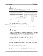
Table3-5 Illustration for external ports of dry contact communication board
1~3P
Inverter fault
4~6P
Battery low-voltage
7~9P
Maintenance bypass
10~12P
Inverting
13~15P
Overload
16~18P
Mains fault
19~21P
Bypass status
22~24P
Fan fault
25~27P
Anti-reverse feedback contactor
3.9.4
SNMP Card (optional)
It realizes the remote control for input voltage, frequency, output voltage, output voltage, frequency,
load, etc. of UPS, and it also can achieve remote control for power on/off.
Before leaving factory, the controlling wire of the UPS has been fixed on the installation port which
marked with SNMP. When installing, it only needs to connect the controlling wire and SNMP card.
3.9.5
Battery Switch
The UPS is equipped with a battery switch.
3.9.6
Anti-reverse Feedback Contactor (Included on “P”Models)
If the main power supply cannot be used, voltage or energy inside the UPS may be reversed (feedback)
to any input terminal directly or indirectly and generate reverse feedback electricity (back-feed). To
decrease the electric shock caused by reversed feedback, it is necessary to have an anti-reverse feedback
device on Parallel-Connectable (P-Series) models so the device meets the IEC62040-1-2 Standards.
Summary of Contents for NE Series
Page 1: ...User Manual NE Series 20 30kVA...
Page 2: ......


