


-11-
Assembly Instruction
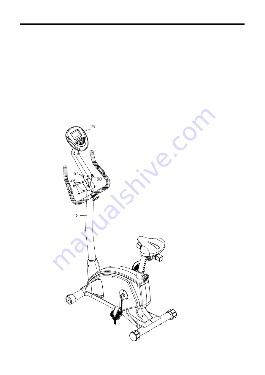
FIGURE 7
Step 1:
Connect the Pulse Wires (64) and Extension Wire (58) to the wires out from the Console
(15). Secure Console (15) to Console Tube(2) using four Screws (39).
Note: The four Screws(39) will already be installed into the back of Console (15) when
you remove it from the box.
FIGURE 7
Summary of Contents for 350U-AT
Page 1: ...350U AT Upright Bike OWNER S MANUAL...
Page 24: ...24 Monitoring Your Heart Rate...
Page 25: ...25 Exploded View...


