


19
114794F – Install/User Manual
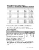
Table 5.1 Battery Torque
Battery Type
Torque
NP55-12B
Torque to 35 in lbs. (3.95 Nm)
LPL12-55-T9
Torque to 35 in lbs. (3.95 Nm)
XTV-12550
Torque to 120 in lbs. (13.58 Nm)
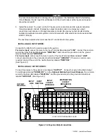
Follow these steps to connect the cables:
NOTE: For standard 90-minute runtimes, 1000W, 1600W, 2200W and 2800W models
have only one battery string.
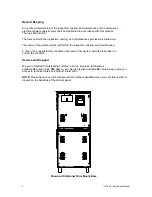
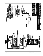
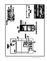
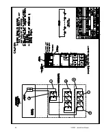
Using the battery-wiring diagram, determine which batteries belong to each shelf.
1. Connect the cable from the Battery Terminal block
NEG. (-)
to the first battery neg. (-).
Clean the cable connectors with the wire brush before you make the battery connections.
NOTE: As you carry out the following step, use these guidelines:
If you are using conductive grease, apply a thin coating of high-temperature
conductive grease on each post and every cable connector before you assemble
and torque the connection to slow corrosion.
2. In the battery string, connect the battery cables between the batteries as shown in the
battery-wiring diagram (positive terminal to negative terminal). Connect battery
temperature probe (labeled TEMP PROBE) to the front battery terminal (+) on the
second battery in from the right on the top shelf (See Table 5.2).
Torque the connections to the value shown for your battery in Table 5.1.
3. Connect the battery cables from one shelf to the next as shown on the battery-wiring
diagram. (1600W – 2800W Systems only)
CAUTION
Hazardous
voltage is present! System batteries are high current sources. These
batteries can produce dangerous voltages, extremely high currents, and a risk of
electric shock.
4. Connect the cable from the Battery Terminal Block
POS. (+)
to the last battery pos. (+).
5. Next, using the voltmeter to check the DC voltage between the battery positive (+) and
the battery negative (-) on the battery terminal block inside the electronics cabinet. This
voltage should be approximately the battery voltage record on the unit ID label. If it is
greater than + or – 5% Vdc, review the battery wiring diagram. Correct any wiring errors
and recheck the DC voltage; do not go on until your measurement is or –
5% Vdc. If the measurement is too high and you cannot find the cause of the problem,
call SERVICE.
CAUTION
If you do not verify that voltage and current direction are correct, the equipment may fail.
Summary of Contents for EM Series
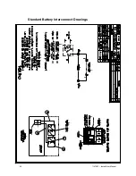
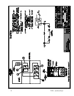
Page 23: ...22 114794F Install User Manual Standard Battery Interconnect Drawings ...
Page 24: ...23 114794F Install User Manual ...
Page 25: ...24 114794F Install User Manual ...
Page 26: ...25 114794F Install User Manual ...
Page 27: ...26 114794F Install User Manual Optional Battery Interconnect Drawings ...
Page 28: ...27 114794F Install User Manual ...
Page 29: ...28 114794F Install User Manual ...
Page 30: ...29 114794F Install User Manual ...
Page 47: ...46 114794F Install User Manual Figure 9 3 ...
Page 48: ...47 114794F Install User Manual Figure 9 4 ...
Page 49: ...48 114794F Install User Manual SECTION 10 OPTION DRAWINGS ...
Page 50: ...49 114794F Install User Manual ...
Page 51: ...50 114794F Install User Manual ...
Page 52: ...51 114794F Install User Manual ...
Page 53: ...52 114794F Install User Manual ...
Page 54: ...53 114794F Install User Manual ...
Page 55: ...54 114794F Install User Manual ...
Page 56: ...55 114794F Install User Manual CENTRAL EMERGENCY SYSTEM FAULT ALARM ...
Page 57: ...56 114794F Install User Manual ...