


18
114794F – Install/User Manual
Battery Cable Sizing
The battery cables or wires used are Number 10-Gauge (5.26 mm
2
) for all applications:
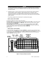
DC Disconnect
The system has a Battery Circuit Breaker inside the cabinet; this circuit breaker lets you
remove DC power from the batteries.
Installing and Connecting the Batteries
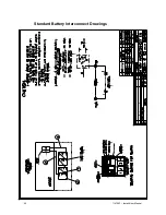
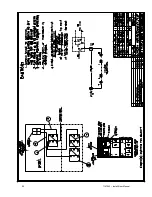
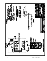
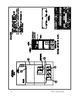
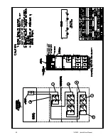
Battery Wiring Diagram
You should have received a battery-wiring diagram with your system. This battery-wiring
diagram shows how you should install the batteries; make terminal and circuit breaker
connections. Use the diagram as you follow the steps below.
Location
The system batteries belong inside the unit. Before you start installing the batteries, you must
install the system in its permanent location. If you have not already done this, see “Location
Guidelines” on page 8 to choose a location.
CAUTION
To prevent damage to your equipment, do not move the system after the batteries are
installed.
To make sure a location is acceptable for the system, review the requirements in Section 3.
Arranging the Batteries
NOTE: As you arrange the batteries, you must be wearing the required safety
equipment.
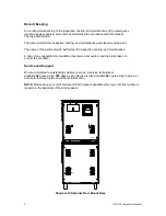
Arrange the batteries in the cabinet only as shown in the battery-wiring diagram. This
arrangement is designed to maximize airflow around the batteries. The cabinets are
designed so that battery cases should never touch. Air should be free to circulate. Clean
the entire surface of all battery terminals with the wire brush before you install the
batteries to create good contact points.
Load the batteries into the system. Starting with the bottom shelf, load one shelf at a
time.
CAUTION
Never install the batteries in an airtight enclosure.
Battery Cables to the electronics battery terminal block are factory installed.
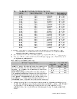
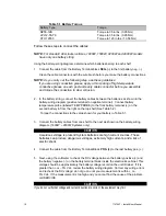
Torque Wrench
When you make battery terminal connections, use the torque wrench to tighten the
battery terminal connections securely. You can find out what torque value to use by
finding the battery number on the front of the battery. Then, use Table 5.1 to find the
torque value for that battery.
Summary of Contents for EM Series
Page 23: ...22 114794F Install User Manual Standard Battery Interconnect Drawings ...
Page 24: ...23 114794F Install User Manual ...
Page 25: ...24 114794F Install User Manual ...
Page 26: ...25 114794F Install User Manual ...
Page 27: ...26 114794F Install User Manual Optional Battery Interconnect Drawings ...
Page 28: ...27 114794F Install User Manual ...
Page 29: ...28 114794F Install User Manual ...
Page 30: ...29 114794F Install User Manual ...
Page 47: ...46 114794F Install User Manual Figure 9 3 ...
Page 48: ...47 114794F Install User Manual Figure 9 4 ...
Page 49: ...48 114794F Install User Manual SECTION 10 OPTION DRAWINGS ...
Page 50: ...49 114794F Install User Manual ...
Page 51: ...50 114794F Install User Manual ...
Page 52: ...51 114794F Install User Manual ...
Page 53: ...52 114794F Install User Manual ...
Page 54: ...53 114794F Install User Manual ...
Page 55: ...54 114794F Install User Manual ...
Page 56: ...55 114794F Install User Manual CENTRAL EMERGENCY SYSTEM FAULT ALARM ...
Page 57: ...56 114794F Install User Manual ...