


13
114794F – Install/User Manual
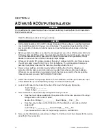
SECTION 4
AC
I
NPUT
&
AC
O
UTPUT
I
NSTALLATION
WARNING
Only qualified service personnel (such as a licensed electrician) should perform the AC installation.
Risk of electrical shock.
Read the following cautions before you continue.
CAUTION
•
Unit contains hazardous AC and DC voltages. Because of these voltages, a qualified electrician
must install the system, AC line service, and batteries. The electrician must install the AC line
service according to local and national codes and must be familiar with batteries and battery
installation.
•
Before you install, maintain, or service the unit, always remove or shut off all sources of AC and
DC power and shut off the system. You must disconnect AC line input at the service panel and
turn off the Installation Switch, open Main AC Input Circuit Breaker and open Battery Circuit
Breaker to make sure the unit does not supply output voltage.
•
Whenever AC and/or DC voltage is applied, there is AC voltage inside the unit; this is because
the unit can supply power from AC line or from its batteries. To avoid equipment damage or
personal injury, always assume that there may be voltage inside the unit.
•
Remove rings, watches, and other jewelry before installing the AC wiring. Always wear
protective clothing and eye protection and use insulated tools when working near batteries.
Whenever you are servicing an energized unit with the door open, electric shock is possible;
follow all local safety codes. TEST BEFORE TOUCHING!
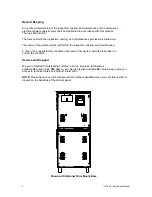
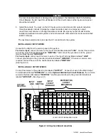
1. Remove the cabinet’s front panel(s). Make sure the installation switch is off, the Main AC Input
Circuit Breaker is open, and the Battery Fuse(s) is removed inside the unit.
2. Look at the ID label on the inside of the door. Write down the following information:
Input Voltage: ___________
Output Voltage: ___________
3. Now, make sure the input and output voltages are what you need.
•
Does the input voltage available for the system at the AC service panel match the input
voltage shown on the unit’s ID label?
Service Panel Voltage = _____________ Input Voltage ___Yes /___No
•
Does the output voltage on the ID label match the voltage for your loads (protected
equipment)?
Load Voltage = ______________ Output Voltage ___Yes/___No
If you answered NO to either of the preceding questions, call SERVICE.
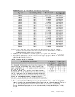
4. Now, use the information you wrote down in Step 2 to find the correct circuit breaker for the service
panel that is for your system.
Summary of Contents for EM Series
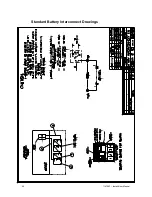
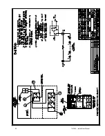
Page 23: ...22 114794F Install User Manual Standard Battery Interconnect Drawings ...
Page 24: ...23 114794F Install User Manual ...
Page 25: ...24 114794F Install User Manual ...
Page 26: ...25 114794F Install User Manual ...
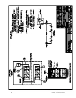
Page 27: ...26 114794F Install User Manual Optional Battery Interconnect Drawings ...
Page 28: ...27 114794F Install User Manual ...
Page 29: ...28 114794F Install User Manual ...
Page 30: ...29 114794F Install User Manual ...
Page 47: ...46 114794F Install User Manual Figure 9 3 ...
Page 48: ...47 114794F Install User Manual Figure 9 4 ...
Page 49: ...48 114794F Install User Manual SECTION 10 OPTION DRAWINGS ...
Page 50: ...49 114794F Install User Manual ...
Page 51: ...50 114794F Install User Manual ...
Page 52: ...51 114794F Install User Manual ...
Page 53: ...52 114794F Install User Manual ...
Page 54: ...53 114794F Install User Manual ...
Page 55: ...54 114794F Install User Manual ...
Page 56: ...55 114794F Install User Manual CENTRAL EMERGENCY SYSTEM FAULT ALARM ...
Page 57: ...56 114794F Install User Manual ...