


15
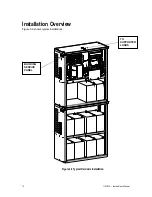
114794F – Install/User Manual
CAUTION
To prevent electrical shock or damage to your equipment, the Installation Switch, the Battery
Circuit Breaker, the AC Input Circuit Breaker and the circuit breaker at the input service panel
should be turned off.
8. Install the conduit. You must run the AC input service conductors and AC output conductors
through separate conduits. Emergency output conductors and non-emergency output
conductors must also be run through separate conduits. Emergency output circuits shall be
installed in dedicated conduit systems and not shared with other electrical circuits as described
in NEC 700-9(b).
The next step explains where to make the AC connections to the system.
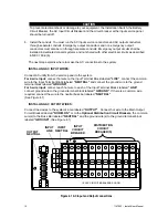
INSTALLING AC INPUT WIRES:
Connect AC utility from the service panel to the system.
For 2-wire input:
connect hot wire to the Input Terminal Block labeled
“LINE”
, connect the common
wire to the Input Terminal Block labeled
“NEUTRAL”
and connect the ground wire to the ground
terminal block labeled
“GROUND”
.
For 3-wire input:
connect each hot wire to each of the Input Terminal Blocks labeled
“LINE”
,
connect ground wire to the ground terminal block labeled
“GROUND”
. If there is a common wire
required, connect the wire to the neutral buss bar labeled
“NEUTRAL”
.
(See Figure 4.1)
INSTALLING AC OUTPUT WIRES:
Connect load wires to the system’s area labeled
“OUTPUT”
. Connect hot wire to the Main Output
Circuit Breaker labeled
“NORM. ON”
or to the
Optional Distribution Circuit Breakers
, the common
wire(s) to the Buss Bar labeled
“NEUTRAL”
and the ground wire(s) to the ground terminal block
labeled
“GROUND”
. (See Figure 4.1)
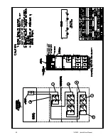
Figure 4.1 AC Input and Output connections
OUTPUT
NEUTRAL
INPUT
CIRCUIT
BREAKER
DISTRIBUTION
CIRCUIT
BREAKER(S)
1-POLE CIRCUIT BREAKERS SHOWN
INPUT
NEUTRAL
INPUT
LINE
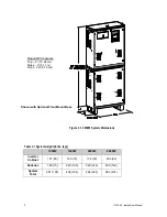
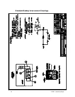
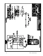
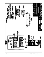
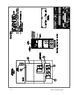
Summary of Contents for EM Series
Page 23: ...22 114794F Install User Manual Standard Battery Interconnect Drawings ...
Page 24: ...23 114794F Install User Manual ...
Page 25: ...24 114794F Install User Manual ...
Page 26: ...25 114794F Install User Manual ...
Page 27: ...26 114794F Install User Manual Optional Battery Interconnect Drawings ...
Page 28: ...27 114794F Install User Manual ...
Page 29: ...28 114794F Install User Manual ...
Page 30: ...29 114794F Install User Manual ...
Page 47: ...46 114794F Install User Manual Figure 9 3 ...
Page 48: ...47 114794F Install User Manual Figure 9 4 ...
Page 49: ...48 114794F Install User Manual SECTION 10 OPTION DRAWINGS ...
Page 50: ...49 114794F Install User Manual ...
Page 51: ...50 114794F Install User Manual ...
Page 52: ...51 114794F Install User Manual ...
Page 53: ...52 114794F Install User Manual ...
Page 54: ...53 114794F Install User Manual ...
Page 55: ...54 114794F Install User Manual ...
Page 56: ...55 114794F Install User Manual CENTRAL EMERGENCY SYSTEM FAULT ALARM ...
Page 57: ...56 114794F Install User Manual ...