FW Murphy – CANdrive installation and operation 00-02-0618 revision F 7
th
January 2011 p3/4
Electrical Connection
CANdrive electrical connection is via a 12-
way automotive type receptacle shown right.
CANdrive models are available with the
connector facing forward through the front
label (‘F’ option, e.g. model CDV100F), or
rearward through the epoxy encapsulation
(‘R’ option, e.g. model CDV300R).
1
4
7
10
2
5
8
11
3
6
9
12
An 8-way, 30”/270mm wiring harness is available as
an additional loose item or as part of a CANdrive kit.
For customer-made harnesses, part numbers for the
mating connector plug and pins are as follows:
Murphy
part ref.
Molex
part ref.
Connector plug shell x 1
(1 required per unit)
79.70.1001 03-09-1125
or 03-09-1126
Connector pins, pack of 50
(max 8 required per unit)
79.70.1002 02-09-1104
Terminal functions
Pin Function
1
2
3
Negative DC, power supply
Positive DC, power supply
Negative DC, gauge common return
CANdrive is supplied for use with 12V (7 to 16V) DC
operation. If 24V (19 to 30V) DC operation is required,
push DIP switch S5 to the off (down) position.
Connect a 1 Amp anti-surge fuse in the positive DC line
(pin 2).
Pins 1 and 3 are internally linked: pin 1 is typically used
as a power supply connection; pin 3 is typically used as
a common negative return for the gauge outputs.
4
6
7
Oil pressure gauge output
Coolant temperature gauge output
Tachometer output
Pins 4 and 6 give a variable current output for driving
oil pressure and coolant temperature electric gauges.
The current output versus pressure/temperature is
specific to each gauge type, as selected using DIP
switches S1, S2 and S3 – see Configuration section.
Pin Function
Pin 7 gives a square wave output (0V to battery positive
DC), with a frequency proportional to engine speed.
At 1500 RPM engine speed, the output frequency is
119 Hz (±1%), suitable for driving charge alternator
based tachometers such as the Murphy ATA and ATHA
series. Pin 7 gives no output when engine speed is
below 100 RPM.
Connect each output to the appropriate gauge/
tachometer signal input. Connect gauge/tachometer
negative terminals to battery negative, ideally via
dedicated wiring to terminal 3. (The use of dedicated
return wiring to pin 3, rather than a ground/earth return,
minimises gauge inaccuracies caused by ground noise.)
5
8
CAN Hi
CAN Lo
Connect these terminals to the engine CANbus, taking
care to observe the correct polarity. The CANbus cable
shield/screen is typically connected to ground/earth at
one end only (often at the ECU): refer to the engine
manufacturer’s installation guidelines.
CANbus J1939 specifications require two 120 Ohm
terminating resistors at each end of the network.
CANdrive is supplied with a 120 Ohm network
terminating resistor in circuit. If CANdrive is not
positioned at the end of the CANbus network, switch
out the terminating resistor by pushing DIP switch S4
off (down) – see Configuration section for details.
9
10
11
12
Reserved for future use
Factory use
Factory use
Factory use
These connections are reserved for future use, or are
used in the factory setup of CANdrive. Do not connect
wiring or equipment to these terminals: connection may
result in permanent damage to CANdrive.
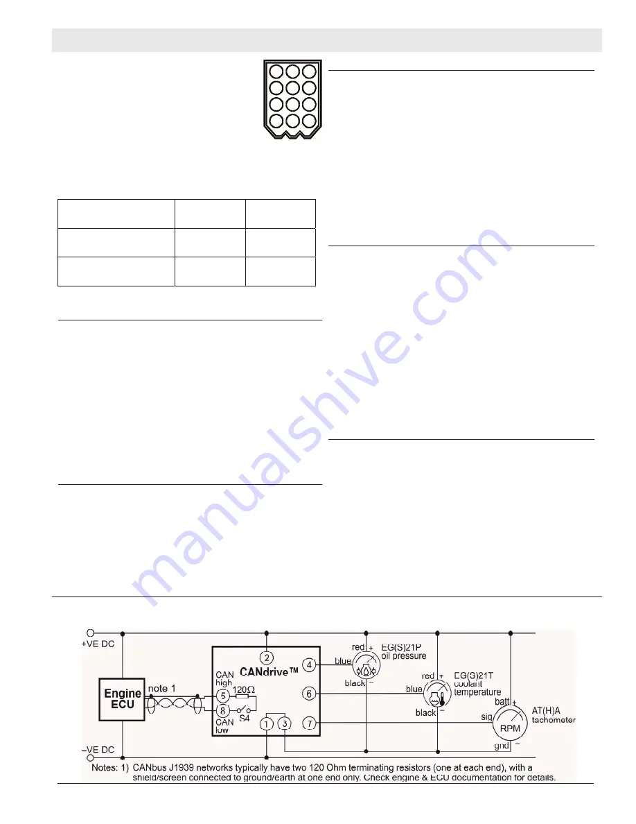
Typical Connection
Shown with Murphy EG(S) series gauges/Swichgages and AT(H)A tachometer.


