MultiWave Sensors Smart Aligner User Manual Download Page 12

To view the User Interface Menu press the Menu Enter button        
Scroll through the menu using the Up/Down buttons    
 There will be a  > next to the selected menu item.  
Press the Menu Enter button       to toggle the selection.  
Use the Up/Down buttons            to continue  through the menu.  
When finished go to EXIT and press  the Menu Enter button  
The item(s) selected will be saved. 

If you are having problems connecting to 
WiFi you can select a specific channel.  
AUTO: Selects the best available channel 
automatically. 

LOCN

 = LOCATION (Latitude & Longitude) 

D.D

: Decimal Degrees 

DM.M

: DegreesMinutes.DecimalMinutes 

DM.S.S

: Degrees Minutes Seconds 

EVENTS

: Such as when a solution is 

calculated there will be a beep. 

BTNS

: When a button is pressed there will 

be a beep. 

Laser

: TruPulse 200 Laser Rangefinder. 

Used for Laser AGL measurement. 

User Menu  

11 

Viewing the Diagnostic and Information Menu  

12 

Diagnostic and other Information can be viewed by pressing the Up/Down buttons          from the main screen 
Latitude, Longitude, Elevation, AGL, Tilt, Roll       (Information) 
Firmware version, Serial Number, WiFi channel  (Information) 
GLN and GPS Satellite information                          (Diagnostic) 
CSEP, HDOP, GPS>50, GLN>50                                 (Diagnostic) 
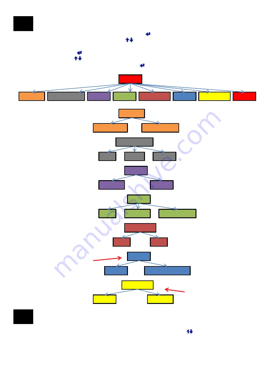
  

MENU 

AZIMUTH 

LOCN FORMAT 

UNITS 

SOUND 

BACKLIGHT 

WIFI CH 

DATA PORT 

EXIT 

AZIMUTH 

TRUE NORTH 

GRID NORTH 

LOCN FORMAT 

D.D 

DM.M 

DM S.S 

SOUND 

OFF 

EVENTS 

BTNS &EVNTS 

UNITS 

METERS 

FEET 

BACKLIGHT 

ON 

OFF 

WIFI CH 

CHANNEL 1 TO 11  

AUTO 

DATA PORT 

DATA 

LASER 

12 

Summary of Contents for Smart Aligner

Page 1: ...USERS GUIDE V1 1 January 2015...

Page 2: ...13 1 Smart Aligner App Flow 13 13 2 App Detailed Description 14 13 3 Quick Measure 14 13 4 Site Survey 15 13 5 Report Example 20 13 6 Settings 21 13 7 Difference Between iOS and Adroid App 21 Section...

Page 3: ...ing for Smart Aligner Multiwave 1 Safety 2 When transporting carrying the Smart Aligner System up a tower follow all relevant safety procedures and requirements Always use the tether lines as describe...

Page 4: ...within Smart Aligner Tool For measuring Azimuth Tilt Roll and Position of Antenna Slot for Options Laser Rangefinder for measuring AGL AIR21 Mounting Bracket Custom Brackets Universal Mounting Bracket...

Page 5: ...sition Stored position to 90 OR Stored Position to 90 Charging Port Port for Wall or Car Charger User Interface LCD Screen Menu Buttons and Power Button Tether Line Pin Attaches to Bracket Mounting Sc...

Page 6: ...ing Screw Knob Receptacle Tether Line to mast or other solid location Tether Line Receptacle from Tool Ratchet Strap Fastening Pins Ratchet Strap with hook Ratchet Strap Fastening Pins Ratchet Strap h...

Page 7: ...cing Tool Dowel Pin Receptacles for Right facing Tool Dowel Pin Receptacles for Back facing Tool 1 Tether the Bracket to a solid location 2 Set the Bracket on the backplane of the antenna as shown Kee...

Page 8: ...Right or Left side of antenna Tool facing Front on Bracket Arms Right T 7 8 Right or Left side of antenna Tool facing Right on Bracket Arms Forward 9 10 Right or Left side of antenna Tool facing Righ...

Page 9: ...ors in the Bracket and Tool detect the configuration and automatically compensate the Azimuth Tilt and Roll of the antenna The different configurations are useful when there are mechanical constraints...

Page 10: ...racket 3 Tighten the Mounting Screw Knob on the Tool 4 Rotate Short Arm clockwise till you feel hear it click in and engage 5 Rotate the Long Arm counter clockwise till you feel hear it click in and e...

Page 11: ...Forward shown Left T Small Arm Left Long Arm Left Right T Small Arm Right Long Arm Right Folded Small Arm Folded Long Arm Forward 1 2 Tilt deg BAT Battery indicator 3 GPS Integrity Value from 0 to 10...

Page 12: ...utes Seconds EVENTS Such as when a solution is calculated there will be a beep BTNS When a button is pressed there will be a beep Laser TruPulse 200 Laser Rangefinder Used for Laser AGL measurement Us...

Page 13: ...s for each of the cases Smart Aligner App flow Connect by WiFi to Tool Run Smart Aligner App Quick Measure Site Survey Settings User can view in real time Azimuth Tilt Roll Latitude Longitude Elevatio...

Page 14: ...BAT Tool battery life Five bars represent around 10hrs of battery life AGL HEIGHT The Laser can be used to measure AGL HEIGHT and will be displayed here When Screenshot is selected an Image Notes scre...

Page 15: ...s selected a keyboard will be displayed Information is added or viewed by scrolling Sector Position Target Azimuth Azimuth Tolerance See Advanced section Target Mechanical Tilt Target Mechanical Roll...

Page 16: ...tion Press Verify During verification the Tool is calculating the average Azimuth The following message will be displayed while calculating Screen 5 After Pressing the sec 1 pos 1 Antenna Screen 6 Aft...

Page 17: ...m to the ground and take a shot The Tool will automatically calculate the AGL and will be displayed Screen 10 After entering an AGL from Screen 9 AGL Height displayed here In this example it was a man...

Page 18: ...ort Tapping on More and then Duplicate antenna will allow the user to create a new antenna with the identical information as the chosen antenna The user can then edit the information For example the o...

Page 19: ...Go back to Sites list Screen 19 Tap on Site1 example There are 2 antennas within Site1 Screen 16 After tapping Report Select all in the Antenna list The report can now be emailed See next page for an...

Page 20: ...Report example 13 5 20...

Page 21: ...4 4 or greater the Report generated will be in JPG format For 4 4 and greater the user will have the option to chose JPG but the default Report will be PDF When a JPG Report is generated each antenna...

Page 22: ...ed into the Smart Aligner App The user imports the file and the Antenna Setup information is populated Multiple antennas can be listed It is best to create a blank generic csv file with the App and th...

Page 23: ...degrees 90 to 90 Carrier All characters Contractor All characters Antenna Type All characters Serial Number All characters User Input 1 All characters User Input 2 All characters User Input 3 All char...

Page 24: ...grees 90 to 90 Latitude Decimal degrees or DMS Direction N or S Longitude Decimal degrees or DMS Direction W or E Elevation Decimal degrees Elevation Units m or ft AGL Height Decimal degrees AGL Heigh...

Page 25: ...Save office csv Be sure that it is saved as a csv file and not an xls file For example see entered data example as below 2 Email office csv to your phone 3 Tap and hold office csv in the attachment an...

Page 26: ...ts and it will default to the csv format 1 Enter Site ID as Tolerance as an example 2 Enter a Target Azimuth of 220 as an example 3 Enter an Azimuth Tolerance of 3 as an example 4 Enter the remaining...

Page 27: ...e another type of measurement device and enter the value 1 Connect the Laser Rangefinder Cable to the Tool 2 Connect the Laser Rangefinder to the other end of the cable 3 Press the and select Data Por...

Page 28: ...rs When the battery is finished charging the Tool will shut off There are five indicator bars that each represent two hours of operation When there is just one bar left the App will show it in red Onl...

Page 29: ...AIR 21 Bracket should be firmly attached to the antenna 5 The Tool can then be mounted to the top of the mounting plate Make sure the Tool is tethered to the AIR 21 Bracket Please note that you can m...

Page 30: ...ther to the structure 2 Place the GOGO Bracket over the top the antenna and open the screw knob so that the clamp fits over the vertical fin 3 Once the GOGO Bracket is seated squarely on the antenna s...

Page 31: ...the bar according to climbing safety regulations 16 4 Edge Adapter The Edge Adapter can be used if your antenna has an extended radome edge or mounting grooves on the back plane of the antenna and th...

Page 32: ...C 68 2 6 EMI FCC Part 15 Subpart B 2008 and ICES 003 2004 Mounting Configurations to Antenna Multiple offset positions from bracket forward side backwards on left or right side of antenna Multiple arm...

Page 33: ...t if the chevrons are not lined the message Position Arms will always be displayed PROBLEM Cannot see Smart Aligner in the list of WiFi networks There may be numerous WiFi networks in the area and the...

Page 34: ...or inability to use such product Futhermore MWS shall not be responsible if any MWS authorized dealer has been advised of the possibility of such damages or for any claim by another party The Smart A...

Reviews: