background image

C

ONNECTION

 P

ANEL

4

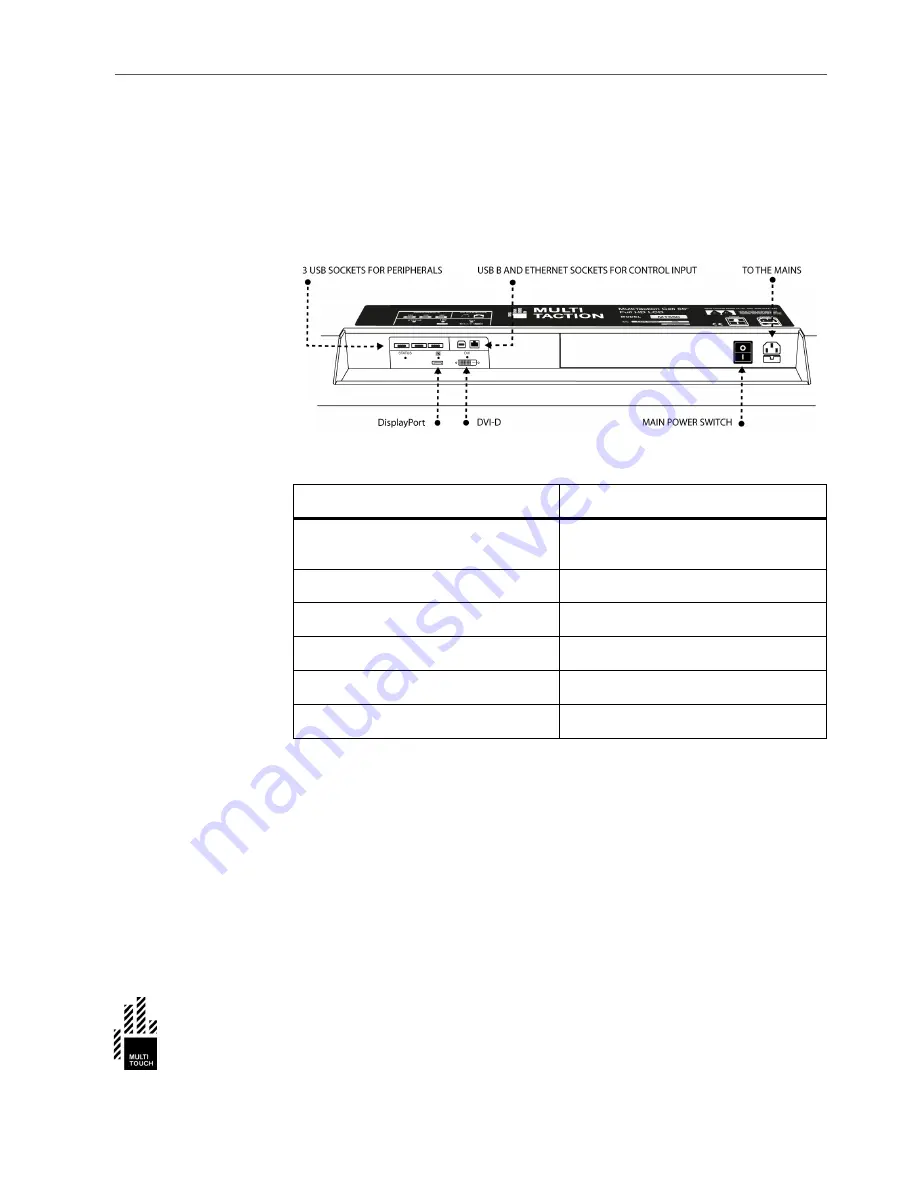
Connection Panel

Connection panel of the Cell is located at the back of the device. It contains 
power switch and the following sockets for connecting the Cell to approriate 
devices and to the mains.

Socket

Purpouse

3 USB Sockets

USB sockets are intended for peripherals of 
the Cell (for example keyboard and mouse)

USB B

For control input

Ethernet

For control input

DisplayPort

Display signal input

DVI-D

Display signal input

Mains

Power connection to the mains supply

Summary of Contents for MultiTaction Cell MT550

Page 1: ...MultiTaction Cell 55 MT550 User Manual v 1 1 ...

Page 2: ...the prod ucts Information in this manual is subject to change without prior notice to product owners For the latest product details and guidelines please visit the product website Copyright 2011 Multitouch All rights reserved NOTE MultiTaction and MultiTouch Cornerstone are trademarks of Multi touch All other trademarks are the property of their respective owners ...

Page 3: ...Trademarks MultiTaction and MultiTouch Cornerstone are trademarks of Multitouch All other trademarks are the property of their respective owners ...

Page 4: ...the product safely Safety Signal Word Explanation DANGER Indicates a hazard with a high level of risk which if not avoided will result in death or serious injury AND OR property damage WARNING Indicates a hazard with a medium level of risk which if not avoided could result in death or serious injury AND OR property damage CAUTION Indicates a hazard with a low level of risk which if not avoided cou...

Page 5: ...s RoHS This MultiTaction Cell complies with the following regulatory standards RoHS EN 55022 EN 55024 IEC 61000 3 2 IEC 61000 3 3 IEC 62471 IEC60950 2005 A1 2009 More information on the complience can be acquired from Multitouch by delivering the S N of the MultiTaction Cell in question ...

Page 6: ...Disposal Guidelines The Cell complies with the European RoHS directive Please consult local authorities and professionals when planning to dispose the Cell ...

Page 7: ... Installation 22 Display wall installations 23 Connecting the Cell 26 Normal Operating Conditions 27 Guidelines for Maximum Performance 28 Software Setup 29 Operations on the MultiTaction Cell 29 Operations on the Application PC 30 Finalizing the Setup 31 More information 31 Computer Recommendations 32 Installation of Cornerstone 33 Calibration 34 Tuning of the Tracking Parameters 34 Finger Tracki...

Page 8: ...ncing interactive possibilities The LCD displays deliver Full HD picture quality have a long life span and need hardly any maintenance Modular means that Cells can be easily connected to each other to create a single large display array showing interactive content split into the various screens while reacting to multiple users touch The system welcomes customization Work on Linux Mac or Windows en...

Page 9: ...ated multi touch LCD display The front glass and LCD package is tuned to allow the integrated optical imaging system to work effectively through it Imaging logic and processing power are embedded in the display unit The illustration below shows the main technologies used in MultiTaction ...

Page 10: ...DIMENSIONS 3 Dimensions The Cell enclosure holds the following dimensions ...

Page 11: ...ing sockets for connecting the Cell to approriate devices and to the mains Socket Purpouse 3 USB Sockets USB sockets are intended for peripherals of the Cell for example keyboard and mouse USB B For control input Ethernet For control input DisplayPort Display signal input DVI D Display signal input Mains Power connection to the mains supply ...

Page 12: ...ing warning labels can be found on the Cell CLASS 1 LED PRODUCT IEC 60825 1 A2 2001 label attached to the back of the enclosure CLASS 2 LED RADIATION warning label IEC 60825 1 A2 2001 attached to metal structure within the enclosure of the Cell ...

Page 13: ...tive Area 1209 x 680 mm Pixel Pitch 0 63 x 0 63 mm Pixel Response Time 8ms grey to grey Brightness 250 cd m2 Contrast Ratio 4000 1 typical Picture Frame Rate 60 Hz Backlight White LED Matrix Array Viewing Angle 178 Touch technology Computer Vision Through Screen Tracking Speed Up to 200 fps IR Source cameras Integrated Backlight Emitter Camera modules IR Wavelength 850 nm Display Safety Glass Temp...

Page 14: ... Click hold and drag Hand Recognition Each finger identified to certain hand Object Recognition Supported with 2D fiducial markers Number of Simultaneous Touch Inputs Unlimited Number of Simultaneous Users Unlimited separate hands Positional accuracy 2mm directional compensation Relative accuracy Sub pixel accuracy Touch Latency 10 ms typical Measured from touch to processed tracking data output O...

Page 15: ... OS X Stackability Up to 24 Cells can be connected to run a single multitouch application Operating Temperature 0 to 35 degrees C Storage Temperature 10 to 60 degrees C Allow at least two hours for temperature normalization before switching on the unit Relative Humidity Non condensing 80 Physical Dimensions 1242 x 713 x 199 mm Bezel width 16 mm bottom sides 17 mm top Weight 40 kg 90 lbs Color Blac...

Page 16: ... amount 250 m3 hour Agency Approvals CE RoHS Compliant Yes Expected Life time Over 60 000 h Warranty 1 year limited See warranty details in this manual Display Unit 1 Power Cords 5 m EUR US GB Digital Video Cable DVI D 5 m USB A B Cable 5 m Cat5e Ethernet Cable 5 m Display Stand Table stand for landscape portrait use Protective autocalibration sheet 1 Alignment rail bits 4 pcs Warranty Card 1 Quic...

Page 17: ... AC Power Cords US GB and German DVI D Monitor cable USB cable Ethernet cable Production Test Report User guide Alignment rail bits 4 pcs Carefully check that you have received all the items before proceeding with the installation of the Cell If your product box is missing items please contact your dealer ...

Page 18: ... to secure it during the transportation Place the container on a clean floor Make sure to have enough space around the container to remove the Cell and place it to the desired loca tion The Cell is to be removed by two persons one lifting from each side TASK 1 Bend all the metal tabs on the bottom of the box 1 2 Remove the container top by lifting it up 2 ...

Page 19: ...UNPACKING THE CELL 12 3 Remove the protective padding on the top of the Cell 1 4 Remove the Cell from the container with help from another person one lifting from each side 2 ...

Page 20: ... installing ensure that the installation and usage environment is suitable the the MultiTaction Cell Proper Environment Choose a well ventilated cool space for setting up the display CAUTION Infrared sources like halogen spots may harmfully interfere with the tracking sensors Keep the Cell away from strong spot light areas CAUTION Intense sunlight can damage the display Place the Cell in a space w...

Page 21: ...ed enclosure if enclosure is used The device is not covered with clothes papers props or other materials which can prevent the proper ventilation of the device Operating temperature Temperature is between the limits specified on the Normal Operating Conditions External factors There are no external factors heating the Cell above the temperature limits External factors can include for example direc...

Page 22: ... can be installed to VESA Mounts Install the Cell to any pedestal or wall mount that conforms to the VESA Mounting Interface Standard TASK 1 Locate the Standard M8 VESA Mount Screw holes on the back panel of the Cell CAUTION Heat build up reduces the systems life and can cause hardware failure Make sure that the cooling and air ventilation properties of the installation location meet the requireme...

Page 23: ... proper air circulation and cooling between the display and walls or panels 2 Select the VESA Mount installation location and install the Cell according to the VESA Mounting Interface Standard Installation type Safe distance between the Cell and walls panels Single Cell at least 10 cm 4 inches Multi Cell at least 15 cm 6 inches ...

Page 24: ...lly enclosed space Risk of device overheating which can lead to critical hardware failure and personal injuries Ensure that the dimensions and setup of the custom enclosure comply with the minimum safety distance requirement 15 cm 6 inches above the stable surface and that the Cell has proper air venti lation cool air in hot air out CAUTION Loosely installed Cell may fall and cause personal injuri...

Page 25: ...t rail from the Cell 3 Firmly attach the Cell to the custom enclosure Do this by using M8 screws and the VESA screw holes of the Cell Align the Cell with the included alignment rail bits Example of custom table with installed Cell Example of custom enclosure with installed Cell ...

Page 26: ...CUSTOM INSTALLATION 19 Example of custom enclosure with a separate space and ventilation system for the computer unit ...

Page 27: ...To avoid the risk choose a desk with a heavy enough structure for the installation install the desk stands according to this manual and ensure that desk will not tip after the installation TASK 1 Choose a sturdy desk for the installation Ensure the desk can bear the weight load of the Cell 45 kg 100 lbs and that the desk will not tip over when the Cell is installed 2 Depending on the installation ...

Page 28: ...e Cell on the desk stands two people required and attach it to the stands with M8 screws VESA screw holes Align the Cell with align ment rail bits M5 screws 4 Ensure that the desk will not tip when the Cell is installed on the desk stands ...

Page 29: ...tal installation of the Cells CAUTION Cells installed too close to each other or too close to walls or panels behind the Cells cause risk of device overheating which can lead to critical hardware failure and personal injuries Leave enough space between the Cells and any walls or panels behind the Cells to allow proper air circulation and cooling Minimum Safety distance for a Multi Cell installatio...

Page 30: ... requirements for the heat control of the Cells Ensure that Cells located in one ventilation space have sufficient intake of cold air typical use for MT550 220 m3 hour Cell The following example of a 4x3 display wall of MT550 Cells provides general guidelines for the design process Front view View from right NOTICE Forced air flow is recommend ...

Page 31: ...MULTI CELL INSTALLATION 24 Isometric view ...

Page 32: ...ns are set connect both the Cell and the computer to the mains supply Ensure there is no stress or tension on any of the connected cables WARNING People can trip over loose and hanging cables causing personal injuries and damage to the Cell Route and fasten all cables out of the way Make the connections with both the display and the computer disconnected from the mains using the appropriate type o...

Page 33: ...ch the lifetime specification of the Cell always use it under the Normal Operating Conditions Operating condition Correct parameters Temperature 0 35 Celsius 32 95 F Optimal performance 20 25 Celsius 68 77 F Humidity non condensing 80 Display pattern A moving picture or regularly changing animation Sunlight No intense sunlight on the display area front panel Infrared sources Do not use in the vici...

Page 34: ...atic images to moving pictures this helps refresh the display s liquid crystal Periodical changes in background color and character are also recom mended Enable a screen saver with moving pictures or a black pattern Generally avoid backgrounds and content with markedly contrasting lumi nance MultiTaction Cells are designed to operate normally for extended periods of time under 20 hours per day Ens...

Page 35: ... each other Operations on the MultiTaction Cell To use the MultiTaction Cell with an external PC you need to connect the Cell and the PC to the same local area network with an Ethernet cable included in the sales package The connection is usually done via an Etherner switch If a switch is not desirable the Ethernet cable can be connected directly from the PC to the Cell Preparations As a preparati...

Page 36: ... will show the current network settings Especially the IP address is important in this case 10 0 0 51 as that is used later for with the PC to set up a network bridge Adjusting Tracking Parameters If you need to adjust the tracking parameters you can press d on you keyboard to view the tracking display in the Calibration view Once the tracking param eters have been set they can be saved by pressin...

Page 37: ...me from the Cell to the PC For example Twinke is very useful for testing this If you want to use Windows 7 touch features you need to install the Windows 7 touch driver Finalizing the Setup Once application PC is getting the coordinates correctly you can unplug the DVI loopback cable and connect the DVI cable from the application computer to the display More information Detailed and up to date ins...

Page 38: ...and hardware The best computer setup depends heavily on the type of application you are building and the software requirements compatibility etc The minimum computer requirements for single Cell installations Ethernet port Intel AMD CPU with clock rate of 2 2 GHz or higher 1 GB RAM 5 GB free hard disk space OpenGL 2 compliant graphics card drivers all modern NVidia ATI cards match this criteria Ch...

Page 39: ... 33 Installation of Cornerstone Multitouch actively develops the Cornerstone software and procedures related to it Please check the latest instructions from the Cornerstone website https cornerstone multitouch fi getting started ...

Page 40: ...n view The marker tracking parameters are the same as the ones for older Cells see https cornerstone multitouch fi cornerstone documenta tion adjusting tracking parameters Automatic Geometry calibration MultiTaction Cells utilize a camera matrix for tracking objects on the display surface During transport and installation the physical positions of the cameras may move by some millimeters which cau...

Page 41: ...tion process takes at most 3 minutes after which the cali bration sheet can be removed from the display On line Resources Calibration For calibration instructions https cornerstone multitouch fi calibration Troubleshooting For troubleshooting instructions https cornerstone multitouch fi troubleshooting Support For online support on MultiTouch Cells https cornerstone multitouch fi support form requ...

Page 42: ...approved by Multitouch Opening the device enclosure causes immediate risk of electrocution severe personal injury and property damage Never open the device enclosure Cleaning the Cell The front glass can be wiped clean with a moist soft cloth Solvents can damage the display area of the Cell Only use mild detergents or none when cleaning the front glass ...

Page 43: ...es and presents the warranty card indicating the date of purchase the name of the Authorized Reseller the model of this Product and the serial number of this Product MultiTouch reserves the right to refuse warranty if this information has been removed obliterated or altered after the originalpurchaseof this Productfrom MultiTouch or the AuthorizedReseller where applicable Buyer shall notify MultiT...

Page 44: ... installation or use not consistent with the instructions and technical or safety standards prescribed in the user manual associated with this Product Accidents acts of nature such as lightning water and fire public distur bances improper ventilation voltage fluctuations or any other cause beyond the reasonable control of MultiTouch Unauthorized modifications of this Product for the purpose of com...

Page 45: ...is warranty is exclusive The sole and exclusive obligation of MultiTouch is to repair or replace the defective Product in the manner and for the period providedabove MultiTouchshall not have any other obligationwith respectto this Product or any part thereof whether based on contract tort and strict liability or otherwise Under no circumstances whether based on this limited warranty or otherwise s...

Page 46: ... repair shall be invoiced by either MultiTouch or the Authorized Reseller in ques tion as the case may be and warranty for the unexpired period shall continue 7 The warranty does not cover the use of the Product s for demonstration purposes 8 The warranty does not cover accessoriesexternal to this Product 9 The Authorized Reseller with whom this Product is registered for warranty service or MultiT...

Page 47: ... SHALL APPLY AFTER THE EXPRESS WARRANTYPERIODS STATED ABOVE AND NO OTHER EXPRESS WARRANTYOR GUARANTYGIVEN BY ANY PERSON FIRM OR CORPORATIONWITH RESPECT TO THIS PRODUCTSHALL BE BINDING ON MULTITOUCH MULTITOUCH SHALL NOT BE LIABLE FOR LOSS OF REVENUE PROFITS OR DATA FAILURE TO REALIZE SAVINGS OR OTHER BENEFITS OR ANY OTHER SPECIAL INCIDENTAL OR CONSEQUENTIAL DAMAGES CAUSEDBY THE USE MISUSE OR INABIL...

Reviews: