background image

Wireless System Manual 

3.3


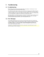
USB Interface 


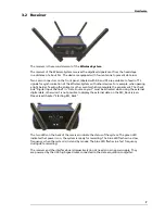
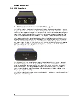
The USB interface board is the third element of the 

Wireless-System

The interface board is connected to the receiver with a MCS Bus cable, which is about 5 m long. 
Longer cables are delivered on request. The advantage is that the interface board can be placed 
near to the data acquisition computer in a different room than the experimental laboratory and 
the test animal will not be disturbed in excess of the experimental setup and the scientist. The 
connection to the data acquisition computer is realized via USB high speed cable, respectively. 

Two additional Lemo connectors are available to feed in TTL signals for synchronization of the 
Wireless-System with other devices, for example when the test animal is passing a light barrier, 
when the animal is feeded or other events, which are manipulating the experiment. The check 
box "Digital Input Channel" in "Data Source Layout" must be activated when using the external 
digital data, otherwise it is not possible to display the external data on the MC_Rack screen.  
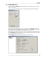
Please read chapter “Starting MC_Rack”. 


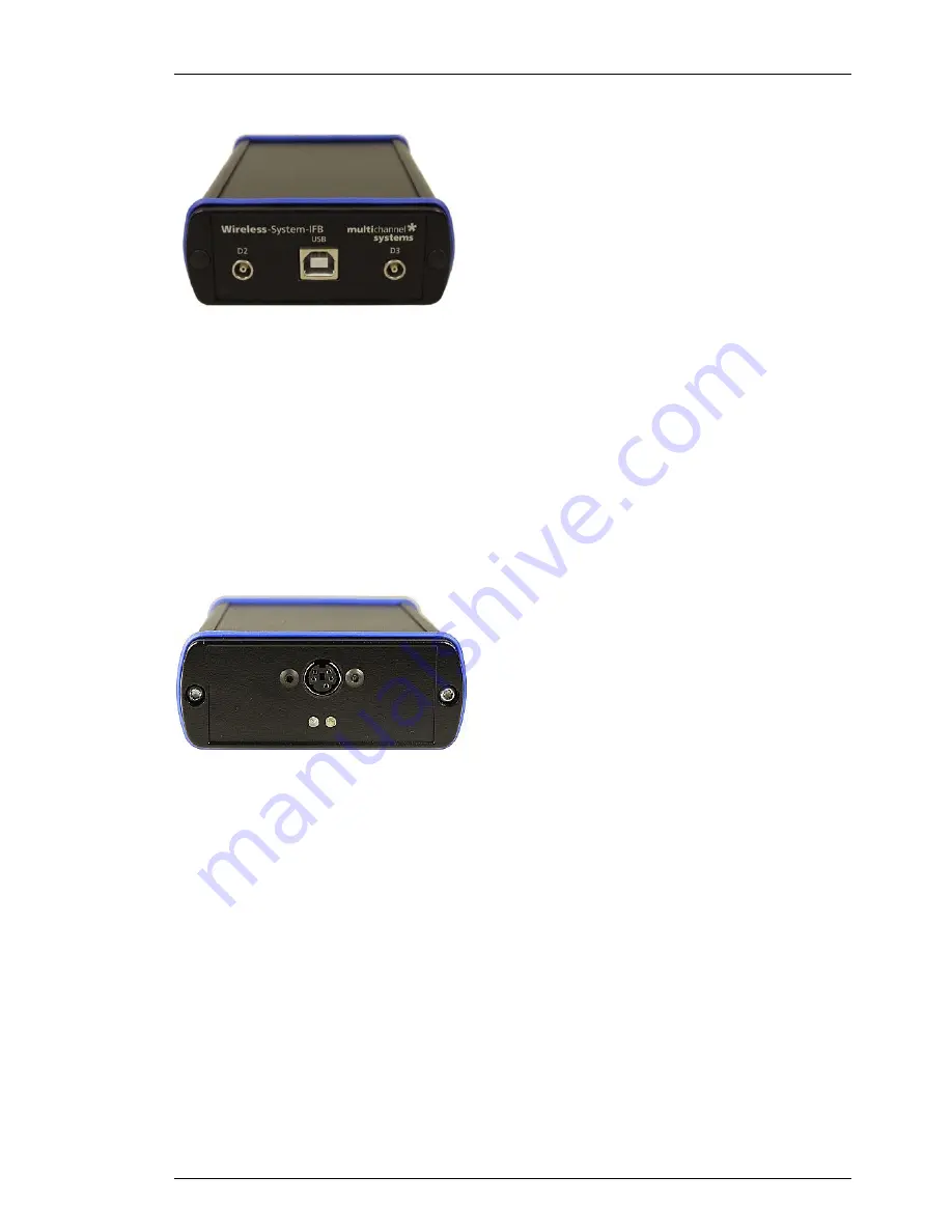
The two LEDs on the back of the interface board indicate the status of the system: The green  
LED indicates that power is on. If the green LED flashes, you have to install  the newest version  
of MC_Rack software, which automatically will update your system with the drivers needed.  
When the hardware is successfully installed, the green LED illuminates stable. The blue LED  
flashes in slow frequency, when the system is in stand by modus. The blue LED flashes in fast 
frequency during data recording. 

The interface board does not need an own power supply. It is powered via USB high speed cable 
by the data acquisition computer. 


Summary of Contents for W16-System

Page 1: ...Wireless System Manual ...

Page 2: ...he publisher and the author be liable for any loss of profit or any other commercial damage caused or alleged to have been caused directly or indirectly by this document 2013 Multi Channel Systems MCS GmbH All rights reserved Printed 16 12 2013 Multi Channel Systems MCS GmbH Aspenhaustraße 21 72770 Reutlingen Germany Fon 49 71 21 90 92 5 0 Fax 49 71 21 90 92 5 11 info multichannelsystems com www m...

Page 3: ...ons 4 Hardware 5 Headstage 5 Receiver 7 USB Interface 8 Software 9 Installing MC_Rack 9 Starting MC_Rack 11 Operating a Wireless System 19 Experimental Setup 19 Operating Modes 21 Troubleshooting 23 Troubleshooting 23 Error Messages 23 Appendix 25 Wireless System Config 25 Technical Support 29 Technical Specifications 30 Pin Layout 32 Power Consumption 33 ME W Signal Generator 34 Contact Informati...

Page 4: ......

Page 5: ...n about the installation and first steps The printed manual and help are basically the same so it is up to you which one you will use The help offers you the advantage of scrolling through the text in a non linear fashion picking up all information you need especially if you use the Index and the Search function If you are going to read larger text passages however you may prefer the printed manua...

Page 6: ...tem includes everything you need Small sized headstage with integrated A D converter digitized transmission and a powerful receiver For controlling the easy to use software package MC_Rack is available With its excellent signal to noise ratio the W4 W8 W16 or W32 Systems are the ideal solution for spikes LFP EEC ECG and ECoG Additional inputs to the receiver allow the synchronization of the data w...

Page 7: ...should be rectified immediately High Voltage Electrical cords must be properly laid and installed The length and quality of the cords must be in accordance with local provisions Only qualified technicians may work on the electrical system It is essential that the accident prevention regulations and those of the employers liability associations are observed Each time before starting up make sure th...

Page 8: ...age installation commissioning operation or maintenance of the device Unauthorized structural alterations to the device Unauthorized modifications to the system settings Inadequate monitoring of device components subject to wear Improperly executed and unauthorized repairs Unauthorized opening of the device or its components Catastrophic events due to the effect of foreign bodies or acts of God 2 ...

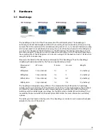
Page 9: ...e for the dimensions and weights of the headstages Thus the headstage is lightweight and reasonable for the free moving laboratory animal Dimensions Weight W in mm D in mm H in mm Weight W4 System 13 antenna 13 5 2 battery W8 System 16 antenna 16 5 3 battery W16 System 16 antenna 16 6 5 4 battery W32 System 16 antenna 16 7 5 5 battery The headstage is designed energy efficient The standard battery...

Page 10: ...r initial testing the Wireless System you do not have to operate with a laboratory animal but you can use a signal generator The ME W System Signal Generator is a convenient tool for the user As a variable substitute for laboratory animals you can use the ME W SG as you would set up a research experiment That means you can test your Wireless System and data acquisition settings without using valua...

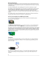
Page 11: ...ulate the experiment The check box Digital Input Channel in Data Source Layout must be activated when using the external digital data otherwise it is not possible to display the external data on the MC_Rack screen Please read chapter Starting MC_Rack The two LEDs on the back of the receiver indicate the status of the system The green LED indicates that power is on the system is ready for recording...

Page 12: ...s passing a light barrier when the animal is feeded or other events which are manipulating the experiment The check box Digital Input Channel in Data Source Layout must be activated when using the external digital data otherwise it is not possible to display the external data on the MC_Rack screen Please read chapter Starting MC_Rack The two LEDs on the back of the interface board indicate the sta...

Page 13: ... following Microsoft Windows operating systems is required Windows 7 Vista or XP English and German versions supported with the NT file system Other language versions may lead to software errors Hardware System of implanted electrodes headstage receiver and interface box The Wireless System Not required for offline analysis or demo mode If no data acquisition is present MC_Rack opens in a simulati...

Page 14: ...rd discs for program files and data storage The provided possibility to make long term experiments with a sample rate of up to 40 kHz needs high memory capacity Please remove data and defragment the hard disc regularly to ensure optimal performance Warning The operating system settings of the data acquisition computer were preconfigured by MCS and should not be changed by the user Changing these s...

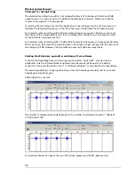
Page 15: ... W8 System MCS WPA8 S N xxxx will automatically appear in the right drop down menu In Source Layout the check box 1 dimensional is predefined and the Number of Channel in total is 8 Enable the check box Digital Input Channel if you want to display external TTL signals feeded into the W8 System via Lemo connectors on receiver and interface board Deselect the check box if you do not need additional ...

Page 16: ...ecording with all eight available channels the sampling rate is limited to 20 kHz Recording with one to four channels only is possible with a sampling frequency of up to 40 kHz Click the Sampling Frequency drop down menu and select the desired sampling rate Click Amplification Gain button Enter The Enter Amplifier Gain dialog appears The fixed amplifier gain of 100 for the wireless headstage is di...

Page 17: ...tch off modus it is not possible to switch a headstage back on via software control The blue LED mounted on the headstage of the W8 System indicates the recording phases It can be switched into three modes via radio button Select Off if the laboratory animal is disturbed by the light Switching off the LED will save a little bit of energy Select Blink and the LED flashes during recording Select On ...

Page 18: ...g with 18 dB at 20 kHz sampling frequency you save approximately 50 mA per hour that means the recording time is 30 minutes longer compared to the time when recording with 0 dB However the transmission power will decrease respectively Starting the W8 System again after switching off via software To switch the headstage back on after pressing the button Switch Off the user has two possibilities Use...

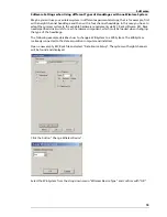
Page 19: ...ments via MC_Rack software MC_Rack needs specified driver units for each hardware component which must be loaded when changing the type of the headstage The following example describes how to change a W8 System to a W4 System The W8 System is already connected to the data acquisition computer and installed Open a new empty MC_Rack file and select Data Source Setup The system with eight channels wi...

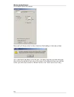
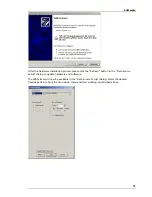
Page 20: ... the headstage is internally switched If you install the W4 headstage for the first time a hardware installation assistant will appear Please follow the installation instructions If the drivers for the W4 System have been installed before ignore this step and click the Refresh button in the Data Source Setup dialog ...

Page 21: ...ase click the Refresh button in the Data Source Setup dialog to update hardware and software The W4 System will now be available in the Data Source Setup dialog Select the desired headstage device from the drop down menu and start working as described above ...

Page 22: ......

Page 23: ...r good signal quality you should use dedicated reference and ground electrodes The reference electrode is used to measure the relative potential differences in relation to the recording electrodes It should be out of a similar or the same material as the recording electrodes and it should be of comparable size The reference is ideally placed near the recording electrodes but not in active tissue T...

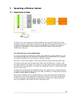
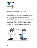
Page 24: ...ed and plugged in properly The battery can be fixed on top of the headstage with a magnet or it can be stored in a special backpack on the back of the animal Connect the wireless headstage to the electrode connector on the skin surface of the test animal Connect the receiver via MCS Bus cable to the interface board and the USB cable to the data acquisition computer The cable between receiver and i...

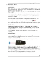
Page 25: ...blue LED on the headstage Stand By Mode To save energy the Wireless System changes from Recording Mode into Stand By Mode immediately after stopping the recording The Stand By Mode allows starting the recording again at any time In this mode the storage battery lasts for up to eighty days depending on the recording time before The Stand By Mode is indicated by a very weak and slow flashing of the ...

Page 26: ... is able to select the desired headstage After recording from the first headstage you can choose the second headstage in the Wireless window the third and the fourth Operating up to four Wireless Systems in parallel with one Computer It is also possible to operate up to four different complete Wireless Systems with one data acquisition computer This way you can experiment with up to four laborator...

Page 27: ... to the safety and service information of chapter Important Safety Advice Multi Channel Systems has put all effort into making the product fully stable and reliable but like all high performance products it has to be handled with care 6 2 Error Messages The headstage sends signals to the receiver in 2 4 GHz frequency band That is why devices working in the same frequency band may disturb the data ...

Page 28: ......

Page 29: ...e the high pass settings of the respective Wireless System Important Please always run the Wireless System Config tool before you start working with a new headstage Main Window The screenshot above shows the main window when the maximal number of four Wireless Systems are connected to one data acquisition computer To each system you can connect up to four headstages In the header of the main windo...

Page 30: ...ardware dialog The Wireless System Config tool is able to assign one headstage after the other to the respective Wireless System Please connect the desired headstage to the battery and press the desired button A B C or D to assign the headstage to A B C or D which is indicated by the green color in the Found button To change your selection you can simply choose a new assignment The information whe...

Page 31: ...hoose another ID When using a second data acquisition computer nearby to record from an additional wireless systems please make sure that the frequency IDs differ from each other Otherwise the systems will interfere To change the high pass filter press the button Change The Change High Pass dialog will open Click the radio button of the desired frequency 0 1 Hz or 1 Hz This information will be per...

Page 32: ...ose your W Type from the drop down menu which possibly is already chosen 4 Now please connect the first headstage to a battery The headstage switches on that means the blue light flickers Important Configure only one headstage at a time 6 Press Select W4 to define the headstage as A B C or D This step determines the frequency band of this particular headstage 7 The established connection is indica...

Page 33: ...e error message text or any other useful information and of the context in which the error occurred The more information on the actual situation you can provide the easier it is to track the problem The serial number of the device You will find it on the bottom side of the main unit The software of MC_Rack version you are currently using On the Help menu click About MC_Rack The displayed dialog bo...

Page 34: ...ior of the system General characteristics Operating temperature 10 C to 50 C Storage temperature 0 C to 50 C Relative humidity 10 to 85 non condensing Headstage Dimensions W x D x H 4 channels 13 mm antennae x 13 mm x 5 mm battery 8 channels 16 mm antennae x 16 mm x 5 mm battery 16 channels 16 mm antennae x 16 mm x 6 5 mm battery 32 channels 16 mm antennae x 16 mm x 7 5 mm battery Weight 4 channel...

Page 35: ...Approx 1 5 g 30 mAh battery Approx 3 g 100 mAh battery Approx 5 g 200 mAh battery Approx 7 g 300 mAh battery Recharging Device Dimensions W x D x H 55 mm x 20 mm x 10 mm Period of charging 1 hour Power USB powered Receiver Dimensions W x D x H 110 mm x 78 mm x 29 mm Frequency band 2 4 GHz Impedance of antennae 50 Ohm Interface Board Dimensions W x D x H 110 mm x 78 mm x 29 mm Control interface USB...

Page 36: ...Wireless System Manual 32 7 4 Pin Layout ...

Page 37: ...Headstage Number of channels 4 8 16 or 32 Dimensions W x D x H W4 13 x 13 x 5 w o antennae in mm W8 16 x 16 x 5 W16 16 x 16 x 6 5 W32 16 x 16 x 7 5 Weight w o battery W4 2 2 g W8 2 9 g W16 3 6 g W32 3 7 g Amplifier integrated in the Headstage Bandwidth 1 Hz to 5 kHz 0 1 Hz on request Resolution 16 bit Sampling rate in kHz per channel Input voltage range 12 4 mV Distance for wireless link 5 m guara...

Page 38: ...es multichannel systems Technical Specifications Batteries Dimensions in mm Weight in g Length Width Height Weight 30 mAh battery 17 11 3 1 5 100 mAh battery 26 19 5 2 3 3 1 200 mAh battery 26 20 4 5 4 6 300 mAh battery 27 5 19 5 5 6 8 Recording Time of batteries in hours at maximal sampling rate on all available channels W4 HS W8 HS W16 HS W32 HS 30 mAh battery 1 0 0 6 0 5 0 4 100 mAh battery 3 2...

Page 39: ...g System multichannel systems Pin Layout of the single row precession socket 1 27 mm round pin Please orientate the headstage as shown on the scheme Channel 1 Channel 2 Channel 3 Channel 4 REF Reference GND Ground W4 Headstage front panel Connector for the storage battery W4 Headstage rear panel Connector for the electrode probe or the ME W Signal generator Connector for W4 Headstage The connector...

Page 40: ...rientate the headstage as shown on the scheme GND Ground REF Reference E1 Electrode 1 Channel 1 E2 Electrode 2 Channel 2 E3 Electrode 3 Channel 3 E4 Electrode 4 Channel 4 E5 Electrode 5 Channel 5 E6 Electrode 6 Channel 6 E7 Electrode 7 Channel 7 E8 Electrode 8 Channel 8 W8 Headstage front panel Connector for the storage battery W8 Headstage rear panel Connector for the electrode probe or the ME W ...

Page 41: ... 3 NC not connected E4 Electrode 4 Channel 4 NC not connected E5 Electrode 5 Channel 5 NC not connected E6 Electrode 6 Channel 6 NC not connected E7 Electrode 7 Channel 7 NC not connected E8 Electrode 8 Channel 8 Guide post GND Ground W8 Headstage front panel Connector for the storage battery W8 Headstage rear panel Connector for the electrode probe or the ME W Signal generator via the adapter ADP...

Page 42: ... Channel 2 Channel 3 Channel 4 Channel 5 Channel 6 Channel 7 Channel 8 Channel 9 Channel 10 Channel 11 Channel 12 Channel 13 Channel 14 Channel 15 Channel 16 REF Reference W16 Headstage front panel Connector for the storage battery W16 Headstage rear panel Connector for the electrode probe or the ME W Signal generator Connector for W16 Headstage The Omnetics connector mates with standard pin conne...

Page 43: ... 7 Channel 5 Pin 19 Channel 17 Pin 31 Channel 29 Pin 8 Channel 6 Pin 20 Channel 18 Pin 32 Channel 30 Pin 9 Channel 7 Pin 21 Channel 19 Pin 33 Channel 31 Pin 10 Channel 8 Pin 22 Channel 20 Pin 34 Channel 32 Pin 11 Channel 9 Pin 23 Channel 21 Pin 35 GND Ground Pin 12 Channel 10 Pin 24 Channel 22 Pin 36 GND Ground W32 Headstage front panel Connector for the storage battery W32 Headstage rear panel Co...

Page 44: ...city of the battery in use by the current drawn by the headstage Please see the following table for the power consumption Example Using a 100 mAh battery with a W4 System sampling at 0 5 kHz with all four channels you have a battery life of approximately 100 mAh 13 8 mA 7 h and 15 min ...

Page 45: ...x x x x x x x x x x x x x x x x x x x x x x x x x x x 40 x x x x x x x x x x x x x x x x x x x x x x x x x x x x x x x x 17 18 19 20 21 22 23 24 RF Output Power dB 0 6 12 18 0 6 12 18 0 6 12 18 0 6 12 18 0 6 12 18 0 6 12 18 0 6 12 18 0 6 12 18 Samplingfrequency kHz 0 1 38 38 38 38 38 38 38 38 38 38 38 38 38 38 38 38 38 38 38 38 38 38 38 38 38 38 38 38 38 38 38 38 0 2 39 4 39 2 39 1 38 8 39 4 39 2 ...

Page 46: ...5 32 1 31 3 30 7 30 5 32 2 31 3 30 8 30 5 32 2 31 2 30 8 30 5 4 40 7 39 37 9 37 4 40 7 39 37 9 37 4 40 7 39 37 9 37 4 40 7 39 37 9 37 4 40 7 39 37 9 37 4 40 8 39 37 9 37 4 40 7 39 37 9 37 4 40 7 39 37 9 37 5 5 44 2 42 2 40 9 40 3 44 2 42 2 40 9 40 3 44 2 42 2 40 9 40 3 44 3 42 2 40 9 40 3 44 3 42 2 40 9 40 3 44 3 42 2 41 40 3 44 3 42 2 40 9 40 3 44 2 42 2 40 9 40 3 10 59 6 55 6 53 51 9 59 6 55 6 5...

Page 47: ... 14 2 14 2 14 5 14 3 14 2 14 2 2 13 9 13 8 13 8 13 7 14 4 14 3 14 2 14 2 15 3 15 14 9 14 9 15 3 15 1 14 9 14 9 4 14 4 14 3 14 3 14 2 15 3 15 14 9 14 9 17 5 17 1 16 8 16 6 17 5 17 16 7 16 6 5 14 8 14 6 14 5 14 5 15 8 15 5 15 4 15 3 18 6 18 17 7 17 5 18 6 18 17 7 17 6 10 15 8 15 5 15 4 15 3 18 6 18 17 7 17 5 24 22 9 22 2 21 9 24 22 9 22 2 21 9 20 18 6 18 17 7 17 5 24 22 9 22 2 21 9 31 3 29 2 28 27 4...

Page 48: ...Wireless System Manual 34 7 6 ME W Signal Generator ...

Page 49: ... to the 20 pin Omnetic connector Connect the wireless headstages W8 and W16 according to the guide posts as shown on the photos beside The orientation of the W32 does not matter Additionally it is possible to connect the MPA8I System to the ME W SG Please insert the MPA8I headstage together with the adapter in correct orientation into the 10 pin single row connector as shown on the photo below The...

Page 50: ...ress n times Signal Source OFF OFF Artificial Sine Wave 1 75 mV 0 005 Hz Note sine waves 1 Hz might not be visible because of the hardware filter bandwidth 1 Sine Wave 0 01 Hz 2 Sine Wave 0 03 Hz 3 Sine Wave 1 25 Hz 4 Sine Wave 12 5 Hz ON OFF Hippocampal Slice EPSP 1 Hippocampal Slice Population Spike 2 Hippocampal Neurons Spikes OFF ON Heart ECG Atrium 1 Heart ECG Ventricle 2 Cardiomyocytes Ventr...

Page 51: ...User Forum provides the opportunity for you to exchange your experience or thoughts with other users worldwide Mailing list If you have subscribed to the Mailing List you will be automatically informed about new ssoftware releases upcoming events and other news on the product line You can subscribe to the list on the MCS web site www multichannelsystems com ...

Page 52: ......

Page 53: ...37 ...

Page 54: ......

Page 55: ...39 8 Index ...

Page 56: ...Wireless System Manual 40 ...

Page 57: ...hed Off Mode 25 R Receiver 8 Antennae 8 LED 8 MCS Bus Cable 8 TTL Signals 8 Reference Electrode 23 S Sampling Frequency 1 Signal Generator 5 Software 11 Starting MC_Rack 12 Data Display 12 Data Source Setup 12 Hardware Tab 12 Amplifier Gain 12 Sampling Frequency 12 Wireless Window 12 T Technical Specifications 35 U USB Interface 9 LED 9 TTL Signals 9 USB Cable 9 W Wireless Headstage 5 W16 5 W32 5 ...

Page 58: ...42 ...
Reviews: