Wireless System Manual
6
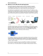
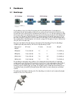
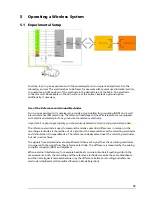
The connector of the headstage is connected to the electrode which is implanted into the brain
of the laboratory animal. The external connector of the implanted electrode is fixed, for example
with dental cement.
For maximum flexibility, MCS offers headstages with connections to all probes on request.
The headstage records analog signals from the electrodes. The integrated A/D converter converts
the analog signals into digital signals, which are sent to the receiver via radio communication
in the 2.4 GHz frequency band. Thus, it enables a long transmission range and low power
consumption at the same time. This makes flexible long time experiments in large environments
possible.
The headstage and the receiver should be placed near to each other in the experimental setup.
They may have a distance to each other of about 5 m without data loss.
First Tests of the Headstage with a ME/W-Signal Generator
For initial testing the Wireless-System you do not have to operate with a laboratory animal,
but you can use a signal generator.
The
ME/W-System Signal Generator
is a convenient tool for the user. As a variable substitute
for laboratory animals you can use the
ME/W-SG
as you would set up a research experiment.
That means you can test your Wireless-System and data acquisition settings without using valuable
biological samples. It has the advantage that you do not need an animal, you reduce the number
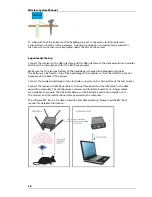
of animal experiments and save laboratory equipment. Please connect the headstage to the signal
generator as shown on the picture. Please read the data sheet in the Appendix for operating the
ME/W-Signal Generator device.
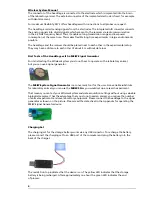
Charging Set
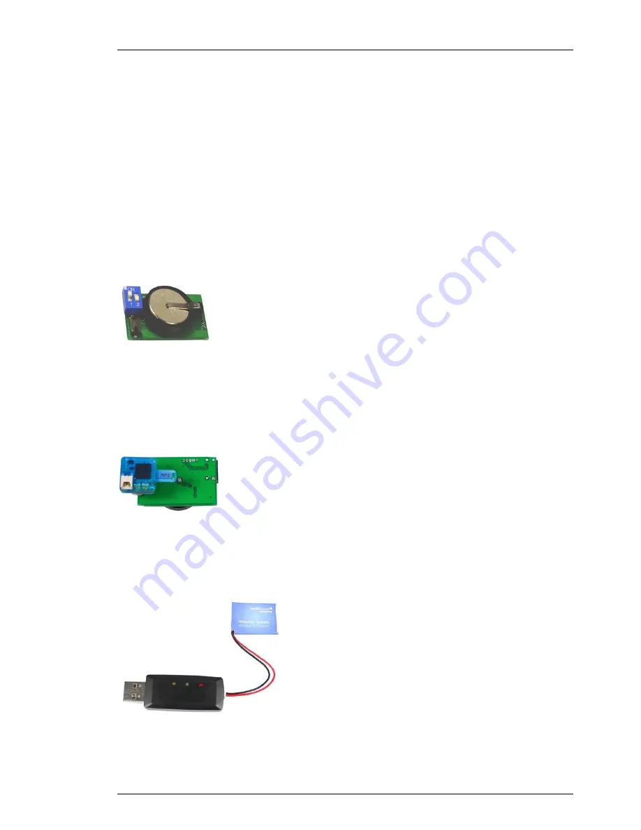
The charging set for the storage battery works via any USB connector. To recharge the battery,
please connect the charging set to an USB port of the computer and plug the battery into the
back of the charger.
The red LED on top indicates that the device is on. The yellow LED indicates that the storage
battery is being recharged. After approximately one hour the green LED indicates the end
of process.
Summary of Contents for W16-System
Page 1: ...Wireless System Manual ...
Page 4: ......
Page 22: ......
Page 28: ......
Page 36: ...Wireless System Manual 32 7 4 Pin Layout ...
Page 48: ...Wireless System Manual 34 7 6 ME W Signal Generator ...
Page 52: ......
Page 53: ...37 ...
Page 54: ......
Page 55: ...39 8 Index ...
Page 56: ...Wireless System Manual 40 ...
Page 58: ...42 ...


