background image


 BULLDOG 65 Hydraulic Steelworker 


25 

8

8

8

8


NOTCHING STATION

NOTCHING STATION

NOTCHING STATION

NOTCHING STATION    

8.1

8.1

8.1

8.1


D

D

D

D

ESCRIPTION

ESCRIPTION

ESCRIPTION

ESCRIPTION


The notching station has a rectangular punch as standard fitting and is supplied with a notch 
table  complete  with  adjustable  side  and  back  stops  which  allow  repetitive  material 
positioning. 
 
Vee notch tooling can be fitted at this work station, or alternatively units can be supplied for 
narrow widths of rectangular or vee shapes; units also available for bar end shaping. 
 
A particular feature of this work station, provides for some punch end units to be fitted. 
 
When notch punch requires sharpening, grind side and front faces of punch only.  
The dies have four cutting edges and should be turned to present new cutting edge. 
 
 
To adjust dies after punch grinding: 
 
1.


Slacken bolster fixing screws and position locking screws. 

2.


Move bolster into new side and front position on punch; 
one side of bolster is adjustable on the die. 

3.


Clearances between punch and die faces should be maintained as follows: 
........at sides of punch  

4/1000

’’ 

........at front of punch 

12/1000

’’ 

Adjust bolster on the two faces accordingly and retighten fixing screws - 
check clearances. 

4.


Release adjustable die blade fixing screws and adjust blade to punch,  
tighten fixing screws and check clearance. 

5.


Ensure fixing screws are tight and that the positioning locking screws have been reset. 


WHEN ORDERING SPARE PUNCHES AND DIES, ALWAYS QUOTE - 

MODEL, TYPE AND SERIAL NUMBER OF MACHINE. 


8.2

8.2

8.2

8.2


N

N

N

N

OTCHING 

OTCHING 

OTCHING 

OTCHING 

T

T

T

T

OOLING 

OOLING 

OOLING 

OOLING 

----


G

G

G

G

ENERAL 

ENERAL 

ENERAL 

ENERAL 

G

G

G

G

UIDES

UIDES

UIDES

UIDES


1.


The quality of cut is an immediate indication of the condition of the tooling. 
Keep sharp, keen cutting edges. 

2.


Check that the notched blank ejects after notching operation, thus avoiding 
any ‘build up’ of slugs. 

3.


Stay within the rated capacity of the machine. 


Summary of Contents for BULLDOG 65

Page 1: ...OGESCHUURSTRAAT 2 B 8850 ARDOOIE BELGIUM _______________________ MUBEA SYSTEME Gmbh Viersenerstraße 3 D 47929 GREFRATH Germany Year of Manufacture Model Type BULLDOG 65 HYDRAULIC STEELWORKER Serial Number Note last 2 digits represent year of manufacture Weight of Machine 2375 lb NETT ...

Page 2: ...fully universal aspects of the Steelworker These instructions give general guide lines for the use of the Steelworker commissioning operating and maintenance and should be carefully studied by the installation engineer and operator before the machine is put into operation Any assistance regarding the machines should first be sought from the supplier or agent MUBEA SYSTEME PINNEY MACHINERY SUPPLY I...

Page 3: ...INGS AND DANGERS 6 3 10 OPERATING MODE SWITCH 7 4 PUNCHING WORK STATION 8 4 1 GENERAL DESCRIPTION 8 4 2 PUNCH TOOLING 9 4 3 PUNCH TOOLING GENERAL GUIDES 9 4 4 PUNCH AND DIE LUBRICATION 10 4 5 PUNCHING CAPACITY 11 4 6 BAR BENDING FACILITY AT PUNCHING STATION 13 4 7 STANDARD PUNCH TOOLING 14 4 8 TYPICAL APPLICATIONS 16 4 9 FLANGE PUNCHING 16 5 SHEARING STATION 17 5 1 DESCRIPTION 17 5 2 SHEAR TOOLING...

Page 4: ...IONAL TOOLING 28 9 4 STROKE ADJUSTMENT 29 9 5 HYDRAULIC SYSTEM 30 9 6 CLEANING 30 9 7 REGULAR MAINTENANCE 30 9 8 HYDRAULIC FLUID 31 9 9 OILING LUBRICANT 31 9 10 MACHINE ARM ADJUSTMENT 32 9 11 PARTS LIST 33 10 CIRCUITS 36 10 1 HYDRAULIC CIRCUIT 36 10 2 ELECTRICAL CIRCUIT 38 11 SPECIAL TOOLING 39 11 1 90 VEE NOTCH TOOLING ARRANGEMENT 39 11 2 WEB PUNCHING ARRANGEMENT FOR I U SECTIONS 39 11 3 LARGE HO...

Page 5: ...al are available from the manufacturer In addition it should be established which persons shall be responsible for the changing and setting of tools and blades and these persons given a more detailed instruction Mubea Systeme machines are supplied complete with various guards and barriers as standard equipment which provide a generally accepted level of guarding when the machine is used for the pu...

Page 6: ...ES APACITIES APACITIES Full details see page 26 27 Punching 11 4 x 15 32 or 11 16 x 5 8 Shearing 8 x 3 4 or 12 x 5 8 Angle Cutting 43 4 x 1 2 51 8 x 1 2 with modified blade Section Cutting 19 16 Round 13 8 Square Notching 3 8 Thickness All capacities are based on materials of 65 000 lbs Tensile Strength Punch Pressure 65 Tons 2 3 2 3 2 3 2 3 S S S STANDARD TANDARD TANDARD TANDARD E E E EQUIPMENT S...

Page 7: ...BULLDOG 65 Hydraulic Steelworker 3 Tool Kit comprisi Tool Kit comprisi Tool Kit comprisi Tool Kit comprising ng ng ng Allen Key 4 5 6 8 10 12 14 17mm 19 and 24mm Open Ended Spanner ...

Page 8: ...TTING UTTING UTTING UTTING For details see page 18 21 This station provides large capacity angle cutting at 90 degrees and lighter angle cutting at 45 degrees Angles between 45 and 90 degrees can be achieved by first cutting at 90 degrees and then flange trimming to the required angle in the shearing station The hold down supports the material thus ensuring a true cut 3 4 3 4 3 4 3 4 S S S SECTION...

Page 9: ...ufficient area all round for easy working and maintenance The machine may be used free standing but bolting to the foundation is recommended With the machine mounted directly on the floor this gives a comfortable working height 3 6 5 Electrical Supply Input wires should arrive at the machine via suitably protected underground supply directly into the electrics box in the base of the machine As an ...

Page 10: ...n leaving the machine MUST be switched off 3 8 3 8 3 8 3 8 O O O OVERLOADING VERLOADING VERLOADING VERLOADING In the event of an accidental overload to the hydraulic circuit the oil will be diverted direct back to the tank via a relief valve until the overload condition is removed IT MUST BE STRESSED HOWEVER IT IS NOT ADVISABLE TO EXCEED THE CAPACITY OF THE MACHINE USING RELIEF VALVE AS A SAFETY V...

Page 11: ... does however have three positions giving the very useful facility that after bringing the arm down by full depression of switch the arm may be held in any position of the stroke by raising the foot to the mid position Remove foot and arm will return to top position 3 10 3 Punch and Die Alignment Should be checked before using and MUST be checked after punch and die changes have been made To check...

Page 12: ...y and without problem and require no additional devices The die is retained in the bolster by a set screw ensure the screw locates correctly on the machined flat on the die when shaped punches and dies are being aligned The punch stripper plate must be correctly adjusted allowing sufficient clearance for placing and removal of material but must NOT restrict the punch stroke ensure the bottom strok...

Page 13: ...unch stripper plate must be adjusted correctly with sufficient clearance to allow positioning and removal of the material being punched 2 Punch holes with sufficient material around the hole so contact is made on both sides of the stripper plate Stripping forces can be severe Unbalanced stripping forces may cause punch breakage 3 Liberal oiling of the punch will considerably lengthen the life of t...

Page 14: ... 219 DUCKHAMS ADFORNOL EP7 Die clearance It is normal practice to aim for a clearance of 10 material thickness Whether clearance is added to the size of the die or deducted from the size of the punch depends on the nature of the work When holes of a given size are required the punch is made to size and the die is made larger Conversely when blanks of a given size are required the die is made to si...

Page 15: ...65 is 28mm 11 16 As an alternative it is possible to calculate a capacity by using the machine constant By dividing the machine constant by the material thickness will give the maximum diameter through that thickness 1 25 4mm 0 2 4 6 8 10 12 14 16 0 22 30 50 70 90 Max Hole Diameter mm Material Thickness mm 45XA 60XA The machine constants are BULLDOG 50 330 BULLDOG 65 420 If you want to calculate t...

Page 16: ...acities are based on materials to be punched having a tensile strength of 45 kg mm 65 000lbs Always keep within the rated capacity of the machine and never attempt to punch a hole smaller in diameter than the thickness of material being punched ...

Page 17: ...ENDING ENDING ENDING ENDING F F F FACILITY AT ACILITY AT ACILITY AT ACILITY AT P P P PUNCHING UNCHING UNCHING UNCHING S S S STATION TATION TATION TATION Press Brake type tooling is available for fitting at the Punching Station giving press brake capacity of 4 x 1 2 IMPORTANT NOTICE HEALTH SAFETY AT WORK ACT SECTION 6 Bending tools must not be fitted to this machine until adequate safety measures h...

Page 18: ...BULLDOG 65 Hydraulic Steelworker 14 4 7 4 7 4 7 4 7 S S S STANDARD TANDARD TANDARD TANDARD P P P PUNCH UNCH UNCH UNCH T T T TOOLING OOLING OOLING OOLING ...

Page 19: ...ion 1 0164405901 Punch holder complete with quick change 1 0164405902 Punch holder 4 9099123540 Socket head screw 1 9079802100 Lock washer 1 0502105904 Quick change fixture 1 5053411638 Punch 9 16 1 3335 Stripper top plate 1 2407 Stripper pillar 2 3336 Stripper head 1 5066021642 Die 19 32 2 2556 Bolster clamp 1 3319 Bolster With the Standard Quick change device you can punch from1 8 up to 1 1 4 Ex...

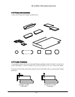
Page 20: ...9 F F F FLANGE LANGE LANGE LANGE P P P PUNCHING UNCHING UNCHING UNCHING The standard bolster 3319 can accomodate flange punching in small sections To achieve the correct back mark it will be necessary to use an eccentric die so as to off set the bolster The front portion of the punch table must be removed and the bolster re positioned for flange punching NORMAL FLANGE PUNCHING ECCENTRIC FLANGE PUN...

Page 21: ... blades require sharpening grind only on the cutting faces max regrinding 3 100 after grinding the blades must be adjusted to a clearance of 4 1000 Adjusting screws have been provided to reset the shear blades the adjusting screws are positioned around blade fixing screws accessable when shear table has been removed Even clearance between top and bottom blades is important along the entire blade l...

Page 22: ... thickness DO NOT Feed bar ends beyond hold down WRONG 5 3 5 3 5 3 5 3 S S S SHEAR HEAR HEAR HEAR B B B BLADES LADES LADES LADES SHEAR BLADE ARM 3409 M12 60 C SK SOCKET SCREW 12mm WASHER 12mm SPRING WASHER M12 FULL NUT 6 OFF EACH SHEAR BLADE BODY 3309 M10 20 S S SCREW DOG PT 9 OFF ...

Page 23: ... the higher support position trim approx 6mm off the end of the section whilst maintaining 45 degrees to vertical position 2 Place the other end into the blade using the left hand support position trim section to length whilst maintaining 45 degrees to face of machine position To achieve other angles of cut between 45 degrees and 90 degrees first cut the angle section to length and then trim the f...

Page 24: ...rew is set for relevant thickness of material being cut 3 Always feed material between blades from hold down side 4 Keep cutting aperture clean small slivers short cuts and any other pieces should be removed from the blade area DO NOT allow mill scale to build up in the blade area 5 Stay within the rated capacity of the machine CAP SCREW M12 35 5 OFF ANGLE BLADE ARM 3549 ANGLE BLADE BODY 3547 S S ...

Page 25: ...n line with the inside web cutting face as shown in sketch Having mounted channel correctly scribe round inside of channel flanges Remove blade from carrier With mark out A continue inner flange line as shown With mark out B continue line from radius square to cutting face Allow a small clearance when grinding to permit easy passage of channel Grinding Grind insert blades to lines scribed shown sh...

Page 26: ...g mounted joist correctly scribe round inside of joist flanges Remove blades from carrier With mark out A continue inner flange line of required With mark out B radius to suit that of sample joist The END FACE may require clearance to permit easy passage of joist for heavy or light sections when blades are in cutting position Grinding Grind insert blades to lines scribed shown shaded in sketch Whe...

Page 27: ...e four screws securing the blade clamps remove blade clamps then withdraw the blades It will be noticed that the arm blade is smaller than the body blade This safeguards incorrect assembly when inserted carrier blades are used Also notice the safety peg there is a safety slot in the arm blade to prevent incorrect positioning BALDE CLAMPS 3327 2 OFF M12 SPRING WASHER 4 OFF CAP SCREW M12 30 4 OFF LO...

Page 28: ...djust the hold down screw if fitted to achieve square cut WHEN ORDERING SPARE BLADES ALWAYS QUOTE MODEL TYPE AND SERIAL NUMBER OF MACHINE 7 2 7 2 7 2 7 2 S S S SECTION ECTION ECTION ECTION T T T TOOLING OOLING OOLING OOLING G G G GENERAL ENERAL ENERAL ENERAL G G G GUIDES UIDES UIDES UIDES 1 The quality of the cut is an immediate indication of the condition of the blades Keep sharp keen cutting edg...

Page 29: ...ng screws and position locking screws 2 Move bolster into new side and front position on punch one side of bolster is adjustable on the die 3 Clearances between punch and die faces should be maintained as follows at sides of punch 4 1000 at front of punch 12 1000 Adjust bolster on the two faces accordingly and retighten fixing screws check clearances 4 Release adjustable die blade fixing screws an...

Page 30: ... SCREW M12 55 K605 70463 6 OFF NOTCH DIE 3537 2 OFF CAP SCREW M16 30 K605 53531 2 OFF CAP SCREW M20 90 K605 5378 2 OFF NOTCH DIE 3536 CAP SCREW M10 30 K605 5335 4 OFF STRIPPER FINGER 3322 2 OFF NOTCH PUNCH 3310 CLAMP 2310 2 OFF M12 PLAIN WASHER K605 7312 6 OFF BOLSTER 4215 TEE NUT M12 K605 2912 6 OFF DIE ADJUSTERS S S SCREW M8 25 DOG K605 5617 6 OFF CAP SCREW M10 25 K605 5334 2 OFF RECOMMENDED DIE...

Page 31: ...ycles min Throat Depth Standard 85 8 Largest Hole 4 Working Height 37 Max Section Flange Punch 4 9 1 2 Shearing Flat Bar 8 x 3 4 Alternative 12 x 5 8 Blade Length 121 2 Angle Flange Trim 31 8 x 3 8 Working Height 37 9 1 3 Angle Cutting At 90 43 4 x 1 2 At 90 with modified blades 51 8 x 1 2 At 45 Mitre 31 8 x 5 16 Working Height 443 4 9 1 4 Section Cutting Round Square Bar 19 16 13 8 Channel Beam 4...

Page 32: ...95 lb Gross Weight 2948 lb Machine Dims 591 2 x 231 4 x 62 Packed Dims 653 8 x 301 2 x 695 8 9 3 9 3 9 3 9 3 A A A ADDITIONAL DDITIONAL DDITIONAL DDITIONAL T T T TOOLING OOLING OOLING OOLING Bending Max Bar Size 6 x 1 2 Punching at Notch Station Max Capacity 3 4 x 1 2 Throat Depth 43 8 Corner Notch Max 4 sq x 1 4 Tube Notch Max Diam 31 4 ...

Page 33: ... Switches should be operated by actuators before hydraulic system pressure i e before cylinder piston reaches end of cylinder full cylinder stroke length Selecting NOTCH on control switch returns notch shear to open operating position Re adjustments Switch selector to PUNCH and make adjustements as above Note Adjustments to stroke limiters can be arranged by switching to the INCH mode of operation...

Page 34: ...lve months 9 6 9 6 9 6 9 6 C C C CLEANING LEANING LEANING LEANING Under normal operation all visible working parts should be regularly cleaned of foreign matter thus preventing excessive wear and possible failure 9 7 9 7 9 7 9 7 R R R REGULAR EGULAR EGULAR EGULAR M M M MAINTENANCE AINTENANCE AINTENANCE AINTENANCE Daily Before starting machine Check fluid level in tank top up as necessary Check oil...

Page 35: ...32 9 9 9 9 9 9 9 9 O O O OILING ILING ILING ILING L L L LUBRICANT UBRICANT UBRICANT UBRICANT Check oil level in pump reservoir daily operate pump 2 3 times daily Castrol Magna DR 220 Shell Tomma T220 B P Energol GHl 220 Mobil Vactra Oil No 4 Esso Febis K220 Lubricant Check Before operating machine the following important checks should be made The Hydraulic fluid is at top level of inspection glass...

Page 36: ...s These are located on the Feed Hold Down Side of the machine as shown in the figure below Adjusting Arm Isolate machine before making any adjustments 1 Slacken locking nuts at the four pad positions only M24 lock nuts 2 Turn adjusting screws clockwise until slight resistance is felt 3 Tighten lock nuts and test movement of arm N B The arm should be adjusted prior to any adjustment of the shear bl...

Page 37: ...15 5000 Hydraulic cylinder 1 13 2079 Hold down adjusting screw 1 14 2093 RAM pressure plate 1 15 2097 notch shear guide 1 16 2307 LMT sw shaft support s e 1 17 2340 Shaft swivel 1 18 2407 Stripper pillar 2 19 2433 Limit switch actuator 2 20 2434 s e lmt boss adj collar 1 21 2435 Rod fixed stop 2 22 2556 Bolster clamps 2 23 2557 Punch retaining ring 1 24 2835 Angle wear bar 1 25 2887 Stripper pivot...

Page 38: ...16 1 51 3427 section blade body 1 52 3428 section blade arm 1 53 4227 P table ext 1 54 3466 Ext support plate 2 55 3536 Notch die 1 56 3537 Notch die 2 57 3547 Angle blade body 1 58 3548 Angle blade body 1 59 3549 Angle blade arm 1 60 3550 Angle blade arm 1 61 3552 Punch stripper mntg blk LH 1 62 3553 Punch stripper mntg blk RH 1 63 3554 cover spacer 1 64 3821 Sub plt 1 65 4242 Notch bolster clamp...

Page 39: ...8 4 Way connector 3 85 K715 2015 Cone LE205 8 86 K715 2016 Bushing LE 305 8 87 K715 5040 Adaptor 50 1202 03 1 88 K715 6010 4mm Oil pipe 2 89 K715 6510 Pressure gauge 1 90 K715 7040 Oil pump 1 91 K715 7085 Elbow 1 92 K905 4020 Bevel gears 2 93 L605 2626 Notch shear guide 5 94 L605 3320 Shear hold down 1 95 L605 4104 Section plate 1 96 L820 1012 Bellhousing 1 97 L820 2013 Coupling 1 98 L820 4510DC D...

Page 40: ... Hydraulic Steelworker 36 10 10 10 10 CIRCUITS CIRCUITS CIRCUITS CIRCUITS 10 1 10 1 10 1 10 1 H H H HYDRAULIC YDRAULIC YDRAULIC YDRAULIC C C C CIRCUIT IRCUIT IRCUIT IRCUIT M 3 12 4 5 6 7 8 9 13 B P A T 1 10 11 2 ...

Page 41: ...c cylinder 1 2 L820 4513 Direction control valve 1 3 L820 45350 Relief valve 1 4 L820 5030 Diffuser 1 5 L920 6000 Tank 54 l 1 6 L820 5020 Suction strainer 1 7 L910 55000 Hydraulic Pump 1 8 Manometer 1 9 3540 Flex Pipe P P 1 10 3539 Flex Pipe A A 1 11 3538 Flex Pipe B B 1 12 3542 Flex Pipe T T 1 13 3541 Flex Pipe S T 1 ...

Page 42: ...RCUIT IRCUIT IRCUIT 5 3 6 4 1 2 KM1 E 1 2 1 F4 V W U 4 E 3 1 3 2 2 2 4 5 2 4 1 3 1 3 F3 2A 24v DC 20V F3 2A 24V F1 5A F2 5A 1 9 10 2 KM1 13 3 2 1 12 11 7 6 B 8 A 8 14 96 95 F4 4 KM1 STOP START REMOTE STOP PUNCH NOTCH NORMAL INCH PUNCH DOWN LIMIT SWITCH PUNCH UP LIMIT SWITCH NEON SOLENOID VALVES SPARE TERMINALS FOOT SWITCH ...

Page 43: ...ITY 8mm THICK CAP SCREW M16 x 60 K605 5358 2 OFF KEY 3151 VEE NOTCH PUNCH 3493 CAP SCREW M12 x 100 K605 53489 2 OFF CAP SCREW M10 x 30 K605 5335 2 OFF CAP SCREW M12 x 55 K605 53481 2 OFF SPRING WASHER M12 K605 7512 4 OFF BOLSTER WASHER M12 2890 2x WASHER M12 K605 7312 2 OFF JACKING PLATE 3506 2 OFF TEE NUT M12 K605 2912 4 OFF DIE ADJUSTERS S S SCREW M8 x 20 K605 5616 6 OFF CAP SCREW M10 x 30 K605 ...

Page 44: ...BULLDOG 65 Hydraulic Steelworker 40 11 2 11 2 11 2 11 2 L L L LARGE ARGE ARGE ARGE H H H HOLE OLE OLE OLE P P P PUNCHING UNCHING UNCHING UNCHING ...

Page 45: ... OFF CAP SCREW M16 40 2 OFF TOP TOOL 9445 2 CAP SCREW M12 50 4 OFF M12 SPRING WASHER 4 OFF BOLSTER WASHER 2890 4 OFF VEE BLOCK 9445 3 VEE BLOCK BASE 9445 5 SS SCREW M10 12 CUP 2 OFF TEE NUT M12 4 OFF When bending always ensure work piece is positioned central on VEE Block to avoid side loading ram Air bending only Adjust down stroke limit switch to avoid unnecessary pressuring of machine Capacity ...

Page 46: ...ction of the requirements for health and safty the accessability and distance between hold downs and blades have been amended To this effect the operation of mitring angle in the angle cutting station requires the following simple hold down adjustment STANDARD HOLD DOWN POSITION REMOVE THREE SECURING SCREWS INVERT HOLD DOWN AS BELOW ROTATE AND SECURE THE HOLD DOWN TO THE MACHINE FOR MITRING Once t...

Page 47: ... 11 612 9 16 50534 11 638 15 64 50534 11 613 37 64 50534 11 641 1 4 50534 11 614 19 32 50534 11 642 17 64 50534 11 615 39 64 50534 11 643 9 32 50534 11 616 5 8 50534 11 644 19 64 50534 11 617 41 64 50534 11 645 5 16 50534 11 618 21 32 50534 11 646 21 64 50534 11 621 43 64 50534 11 647 11 32 50534 11 622 11 16 50534 11 648 23 64 50534 11 623 45 64 50534 11 651 3 8 50534 11 624 23 32 50534 11 652 25...

Page 48: ...16 50534 11 668 61 64 50534 11 671 31 32 50534 11 672 63 64 50534 11 673 1 50534 11 674 1 1 64 50534 11 675 1 1 32 50534 11 676 1 3 64 50534 11 677 1 1 16 50534 11 678 1 5 64 50534 11 681 1 3 32 50534 11 682 1 7 64 50534 11 683 1 1 8 50534 11 684 1 9 64 50534 11 685 1 5 32 50534 11 686 1 11 64 50534 11 687 1 3 16 50534 11 688 1 13 64 50534 11 691 1 7 32 50534 11 692 1 15 64 50534 11 693 1 1 4 5053...

Page 49: ...3 32 50660 21 626 1 1 32 50660 21 676 7 16 50660 21 628 1 1 16 50660 21 678 15 32 50660 21 632 1 3 32 50660 21 682 1 2 50660 21 634 1 1 8 50660 21 684 17 32 50660 21 636 1 5 32 50660 21 686 9 16 50660 21 638 1 3 16 50660 21 688 19 32 50660 21 642 1 7 32 50660 21 692 5 8 50660 21 644 1 1 4 50660 21 694 21 32 50660 21 646 1 9 32 50660 21 696 11 16 50660 21 648 1 5 16 50660 21 697 B For large hole pu...

Page 50: ...0 31 692 17 32 50660 31 636 1 1 4 50660 31 694 9 16 50660 31 638 1 9 32 50660 31 696 19 32 50660 31 642 1 5 16 50660 31 697 5 8 50660 31 644 1 11 32 50660 31 698 21 32 50660 31 646 1 3 8 50660 31 701 11 16 50660 31 648 1 13 32 50660 31 702 23 32 50660 31 652 1 7 16 50660 31 703 3 4 50660 31 654 1 15 32 50660 31 704 25 32 50660 31 656 1 1 2 50660 31 705 13 16 50660 31 658 1 17 32 50660 31 706 27 32...

Page 51: ...BULLDOG 65 Hydraulic Steelworker 47 Operating Instruction Manual MUBEA SYSTEME BULLDOG 65 ...

Reviews: