BULLDOG 65 Hydraulic Steelworker
22
6.4
6.4
6.4
6.4
G
G
G
G
RINDING OF
RINDING OF
RINDING OF
RINDING OF
J
J
J
J
OIST
OIST
OIST
OIST
IIII
NSERT
NSERT
NSERT
NSERT
B
B
B
B
LADE
LADE
LADE
LADE
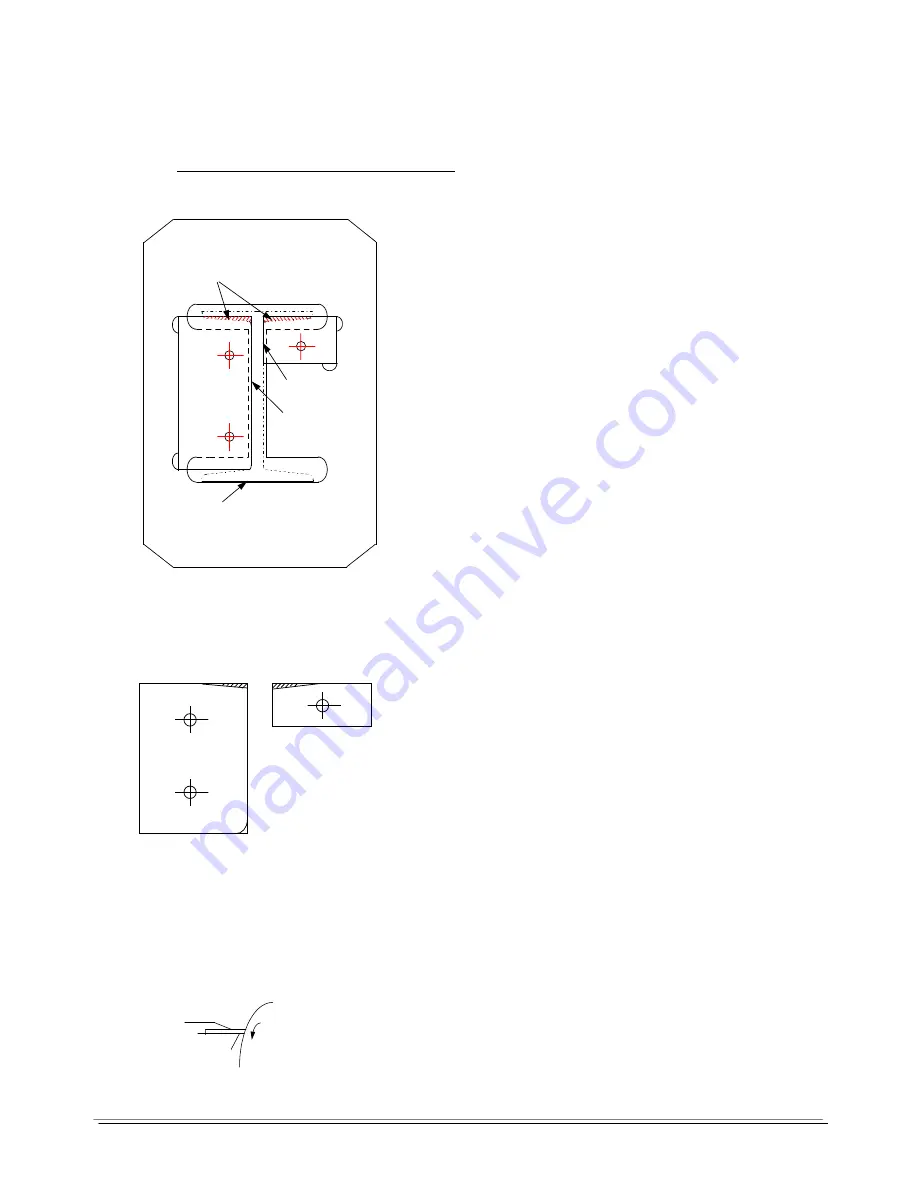
Body Blade
Fit blades to carrier, retain positions with fixing
screws, ensure blades are seating correctly. Mount a
sample of joist, with a cleanly cut end, on to the
blade with the bottom flange in line with BOTTOM
CUTTING FACE and the web square and in line
with WEB CUTTING FACE, as shown in sketch.
Having mounted joist correctly, scribe round inside of joist flanges.
•
Remove blades from carrier.
•
With ‘mark out’ A continue inner flange
line of required.
•
With ‘mark out’ B radius to suit that of
sample joist.
•
The END FACE may require clearance
to permit easy passage of joist for heavy
or light sections, when blades are in
cutting
position.
Grinding
Grind insert blades to lines scribed, shown shaded in sketch.
When hand grinding, if using face of grinding wheel,
ensure angle between face of insert and cutting face
does not exceed 90 degrees.
.
Top Inside Flange cutting
End Face
Web cutting Face
Bottom Flange cutting
A
B
IMPORTANT -
Keep blades cool
when grinding to maintain
correct hardness
Face of
Insert


