MTS Sensors Temposonics V RH5 Series Operation Manual Download Page 3

Temposonics

® 

R-Series 

V

 SSI

Operation Manual

I 3 I

1.  Introduction

1.1 Purpose and use of this manual

Before starting the operation of Temposonics

®

 position sensors, 

read this documentation thoroughly and follow the safety 
information. Keep this manual for future reference!

1/ 

The term “qualified technical personnel” characterizes persons who:

•  are familiar with the safety concepts of automation technology applicable to the  

particular project

•  are competent in the field of electromagnetic compatibility (EMC)

2.  Safety instructions

2.1 Intended use

This product may be used only for the applications defined under item 
1 and only in conjunction with the third-party devices and components 
recommended or approved by MTS Sensors. As a prerequsite of prop-
er and safe operation the product requires correct transport, storage, 
mounting and commissioning and must be operat ed with utmost care. 

 1. The sensor systems of all Temposonics

®

 series are intended 

exclu sively for measurement tasks encountered in industrial, 
commercial and laboratory applications. The sensors are 
considered as system accessories and must be connected  
to suitable evaluation electron ics, e.g. a PLC, IPC, indicator  
or other electronic control unit. 

Foreseeable misuse

Consequence

Wrong sensor connection

The sensor will not work 
properly or can be damaged

Operate the sensor out of the 
operating temperature range

No signal output –
the sensor can be damaged

Power supply is out of the 
defi ned range

Signal output is wrong/
no signal output/ 
the sensor will be damaged

Position measurement is 
infl uenced by an external 
magnetic fi eld

Signal output is wrong

Cables are damaged

Short circuit – the sensor can 
be damaged/sensor does not 
respond

Spacers are missing/ 
installed in a wrong order

Error in position measurement

Wrong connection 
of ground/shield

Signal output is disturbed –
the electronics can be damaged

Use of a magnet that is not 
specifi ed by MTS Sensors

Error in position measurement

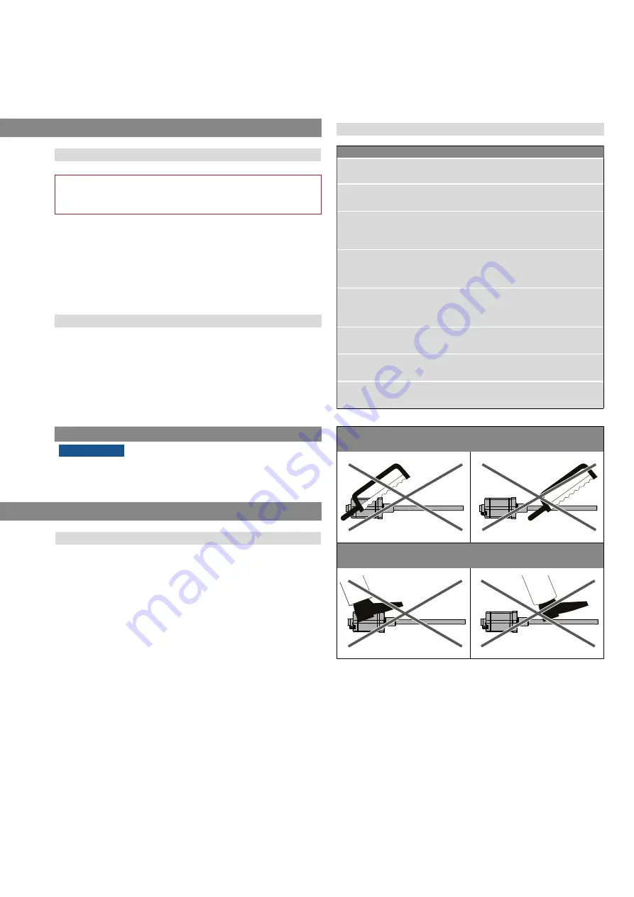
Do not alter the sensor afterwards.

 The sensor might be damaged.

Do not step on the sensor.

 The sensor might be damaged.

2.2 Foreseeable misuse

The content of this technical documentation and of its appendices is 
intended to provide information on mounting, installation and com-
missioning by qualified automation personnel 

1

 or instructed service 

technicians who are familiar with the project planning and dealing with 
Temposonics

®

 sensors.

1.2 Used symbols and warnings

Warnings are intended for your personal safety and for avoidance 
of damage to the described product or connected devices. In this 
documentation, safety information and warnings to avoid danger 
that might affect the life and health of operating or service personnel 
or cause material damage are highlighted by the pictogram defined 
below.

Symbol

Meaning

NOTICE

This symbol is used to point to situations 
that may lead to material damage, but not 
to personal injury.

•  have received adequate training for commissioning and service operations

•  are familiar with the operation of the device and know the information required for 

correct operation provided in the product documentation 

Summary of Contents for Temposonics V RH5 Series

Page 1: ...GENERATION V THE NEW Temposonics R Series V SSI Operation Manual Temposonics Magnetostrictive Linear Position Sensors...

Page 2: ...unit 18 4 7 Electrical connection 19 4 8 Frequently ordered accessories for sensor model RP5 20 4 9 Frequently ordered accessories for sensor model RH5 21 4 10 Frequently ordered accessories for SSI...

Page 3: ...fined range Signal output is wrong no signal output the sensor will be damaged Position measurement is influenced by an external magnetic field Signal output is wrong Cables are damaged Short circuit...

Page 4: ...dous areas The sensors are not suitable for operation in explosion hazardous areas 2 See also applicable MTS Sensors terms of sales and delivery on www mtssensors com 2 5 Warranty MTS Sensors grants a...

Page 5: ...ly option 24 bit can be selected under l Data length j Options 0 Standard 1 Internal linearization a Sensor model R P 5 Profile b Design G Magnet slider backlash free part no 253 421 suitable for inte...

Page 6: ...g direction forward synchronous mode 2 4 Measuring direction forward synchronous mode 3 5 Measuring direction reverse asynchronous mode 6 Measuring direction reverse synchronous mode 1 7 Measuring dir...

Page 7: ...ronics housing NOTICE In this case only option 24 bit can be selected under l Data length j Options 0 Standard 1 Internal linearization 1 2 3 4 5 6 7 8 9 10 11 12 13 14 15 16 17 18 19 20 21 22 23 24 2...

Page 8: ...S 0 0 2 FIR filter 2 measurements S 0 0 4 FIR filter 4 measurements S 0 0 8 FIR filter 8 measurements S 0 0 A No filter error counter 4 cycles S 0 0 C No filter error counter 8 cycles S 0 0 D No filte...

Page 9: ...ing clamps up to 1250 mm 50 in stroke length 1 mounting clamp for each 500 mm 20 in additional stroke length RH5 rod sensor RH5 B Base unit without flange rod assembly 3 socket screws M4 RH5 J M S T S...

Page 10: ...teraction of the magnetic fields releases a torsional strain pulse that propagates the length of the waveguide When the ultrasonic wave reaches the end of the wave guide it is converted into an electr...

Page 11: ...nches Controlling design dimensions are in millimeters and measurements in are in inches Installation of RP5 The position sensor can be installed in any position Normally the sensor is firmly installe...

Page 12: ...46 53 2 09 A F 44 5 1 75 51 3 2 02 RH5 T A V RH5 with threaded flange 16 UNF 3A with raised face example Connection type HXX PXX RXX TXX cable output A F 44 5 A F 1 75 51 3 2 02 25 4 1 Threaded flang...

Page 13: ...nics housing 68 2 68 Null zone 51 2 01 Stroke length 25 5900 1 232 Threaded flange J M22 1 5 6g Magnet 12 7 0 13 0 5 0 01 Dead zone 73 6 2 9 11 7 0 46 RH5 B A V RH5 base unit only for replacement exam...

Page 14: ...tion see chapter 4 6 Replacement of base unit on page 18 Fig 8 Mounting example of threaded flange Fig 9 Sensor in cylinder In the case of threaded flange M18 1 5 6g or M22 1 5 6g provide a screw hole...

Page 15: ...be 15 mm 0 6 in Fig 15 If no other option exists and magnetic material is used observe the specified dimensions Fig 15 Magnet mounting with magnetic material When using magnetic material the dimensio...

Page 16: ...eference edge of mounting Start position 48 5 1 91 End position 66 68 5 2 6 2 7 Stroke length 5000 mm 196 9 in RP5 with magnet slider S N V G Sensor electronics housing Reference edge of mounting Star...

Page 17: ...g on the magnet points to the same direction as the screw in the lid of the sensor electronics housing which is located right of the status LED Fig 20 Alignment of ring magnet for RH5 SSI with interna...

Page 18: ...24 for the sensor designs M S and T The sensor can be replaced without interrupting the hydraulic cir cuit 3 Insert the new base unit Install the ground lug on a screw Tighten the screws Fastening to...

Page 19: ...and electronics earth connections no compensating currents are allowed to flow across the cable shielding Recommendation Install potential compensating leads with large cross section or use cables wi...

Page 20: ...prox 25 g Operating temperature 40 85 C 40 185 F Position magnets Mounting accessories 32 8 1 29 23 8 0 94 13 5 0 53 4 3 0 17 60 140 3 0 12 7 9 0 31 19 5 0 77 1 5 0 06 33 1 3 14 0 55 20 5 0 81 14 9 0...

Page 21: ...0 17 3 2 0 13 15 3 0 6 2 2 0 09 16 4 0 65 2 2 0 09 Block magnet L Part no 403 448 Magnet spacer Part no 400 633 O ring for threaded flange M18 1 5 6g Part no 401 133 O ring for threaded flange 16 UNF...

Page 22: ...r friendly interface for mobile devices and desktop computers See data sheet TempoLink smart assistant document part no 552070 for further information Cables PVC cable Part no 530 032 PUR cable Part n...

Page 23: ...0 Optocoupler 1 6 V 1 nF 1 nF Cable length 3 m 50 m 100 m 200 m 400 m Baud rate 1 MBd 400 kBd 300 kBd 200 kBd 100 kBd Clock T Standard one shot n T MSB Bit n Bit n 1 Bit 3 Clock Data High Low High Low...

Page 24: ...ensor is out of the al lowable range Set the power supply for the sensor to the allowable range Extra magnet Sensor registers more position magnets than set Ensure that the number of position magnets...

Page 25: ...connector of the adapter cable to the connection point labeled OUTPUT SENSOR on the TempoLink smart assistant Fig 35 NOTICE When disconnecting the power supply of the sensor possibly error messages oc...

Page 26: ...ing to the connector wiring in Fig 41 Fig 42 There are two ways to connect the TempoLink smart assistant to a power supply 1 Connection via the plug in power supply with plug adapters Attach the plug...

Page 27: ...cable with the micro USB connector to the port labeled USB on the TempoLink smart assistant Fig 44 2 Next connect the USB type A connector to a free USB port of the computer The USB connection simulat...

Page 28: ...cludes information about the operational settings of the connected sensor Fig 48 To change parameters or to reset the sensor to factory settings the command mode must be started In command mode the se...

Page 29: ...the internal linearization Enabled NOTICE Enabled can only be activated if the sensor was ordered with the option internal linearization Disabled Filter Configuration Setting of the filter for the out...

Page 30: ...16 25 s can be set for this parameter default value 16 s Error Values Setting the values which are transmitted in case of a failure Power Failure Setting the time from when a power failure is output E...

Page 31: ...imum 25 m 30 m 50 m 90 m 150 m 190 m Repeatability 0 001 F S minimum 2 5 m typical Hysteresis 4 m typical Temperature coefficient 15 ppm K typical Operating conditions Operating temperature 40 85 C 40...

Page 32: ...nection Connection type 1 M16 male connector 7 pin or cable output Operating voltage 12 30 VDC 20 9 6 36 VDC Power consumption 1 2 W typical Dielectric strength 500 VDC DC ground to machine ground Pol...

Page 33: ...Operating temperature 40 85 C 40 185 F Humidity 90 relative humidity no condensation Ingress protection IP67 connectors correctly fitted IP68 for cable output Shock test 150 g 11 ms IEC standard 60068...

Page 34: ...nection Connection type 1 M16 male connector 7 pin or cable output Operating voltage 12 30 VDC 20 9 6 36 VDC Power consumption 1 2 W typical Dielectric strength 500 VDC DC ground to machine ground Pol...

Page 35: ...e or several sensors for checking or repair we need you to sign a safety declaration The purpose of this declaration is to ensure that the returned items do not contain residues of harmful substances...

Page 36: ...See Detail C 3 4 16 UNF 2B Thread See Notes 3 And 4 32 in 32 in 125 in B 1 105 in Minimum Full Thread Depth 0 875 in dia 0 015 0 000 0 769 in dia 0 015 0 000 0 500 in dia 0 005 in dia FIM A 45 5 15 1...

Page 37: ...ecreasing from sensor electronics housing to rod end profile end P Parity The parity bit is a check bit that is added to a bit string to detect transmission errors There are even parity and odd parity...

Page 38: ...m JAPAN Zweigstelle Telefon 81 3 6416 1063 E Mail info jp mtssensors com www mtssensors com MTS Temposonics und Level Plus sind eingetragene Warenzeichen der MTS Systems Corporation in den USA MTS Sen...

Reviews: