


Level Plus
®
Tank SLAYER
®
Operation Manual
I
31
I
13.3.2 FM XP
13.3.2.1 Specific Conditions of Safe Use
1. Warning: The equipment contains non-metallic enclosure and
process parts. To prevent the risk of electrostatic sparking, the
non-metallic surface should only be cleaned with a damp cloth.
Painted surface of the equipment may store electrostatic charge
and become a source of ignition in applications with a low relative
humidity <~30% relative humidity where the painted surface is
relatively free of surface contamination such as dirt, dust or oil.
Cleaning of the painted surface should only be done with a damp
cloth.
2. Cables shall be rated > 5°C above maximum ambient
temperature.
3. To maintain the ingress protection rating of IP65, Teflon tape
(3 wraps) or pipe dope shall be used. Refer to Installation
Instructions.
4. The equipment can be installed in the boundary wall between
a Zone 0 area and the less hazardous area, Zone 1. In this
configuration, the process connection is installed in a Zone 0
area, while the transmitter housing is installed in a Zone 1 area.
Refer to installation instructions.
5. Flexible gauges have a minimum bend diameter of 381mm (15
inches).
6. Flamepaths not for repair.
7. The applicable temperature class, process temperature range and
ambient temperature range of the equipment is as follows;
• T3 with Process Temperature Range of -40°C to 150°C
• T4 with Process Temperature Range of -40°C to 135°C
• T5 with Process Temperature Range of -40°C to 100°C
• T6 with Process Temperature Range of -40°C to 85°C
• Ambient Temperature Range -40°C < Ta < 71°C
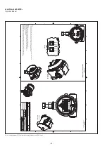
8. When mounting on a MLG (magnetic level gauge) make sure the
electronic head and pressure barrier have a minimum spacing of
5 inches. See Installation Manual for detail.
9. When EPL Ga or Da is required, parts of the equipment containing
light metals (Aluminum or Titanium) shall be protected from
impact so that impact or friction sparks cannot occur, taking into
account rare malfunction. Measures to prevent impact or friction
sparks when using the equipment containing light metals include
but are not limited to:
• Mounting the probe vertically
• No mechanical agitation shall be used
• Use of stilling wells to mitigate effect of agitation.
• Limit rate of change of level to values such that friction sparks
cannot occur
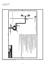
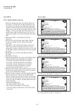
Level Plus Transmitter
MTS Systems Corporation
Sensors Division
3001 Sheldon Drive, Cary, N.C. 27513
FM16US0242X
EXPLOSION PROOF FOR CL. I, DIV. 1, GR. BCD T6...T3
CL. I, ZONE 0/1, AEx db IIB+H2 T6...T3 Ga/Gb
Ta = -40°C TO +71°C ; IP 65
INPUT: 28V (120mA) max
OUTPUT: RS485
WARNING
: DO NOT OPEN WHEN AN EXPLOSIVE ATMOSPHERE IS
PRESENT. FOR ZONE INSTALLATIONS, A SEAL SHALL BE INSTALLED WITHIN 50mm OF
THE ENCLOSURE. FOR DIVISION INSTALLATIONS A SEAL SHALL BE INSTALLED WITHIN 18 INCHES
OF THE ENCLOSUR
INSTALL PER # 651552-1/651595-1
MAX. PRESSURE 1000 PSI (RIGID SENSOR)
MAX. PRESSURE 435 PSI (FLEX SENSOR)
FM
US
APPROVED
P/N 551474- Rev B
R
!
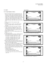
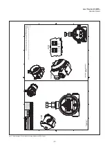
Fig. 26: Explosion proof, FM label, Modbus or DDA Housing Option G, H, or L
Fig. 27: Explosion proof, FM label, Modbus or DDA, Housing Option D, E
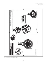
Fig. 28: Explosion proof, FM label, HART
®
, Housing Option G, H, or L
Fig. 29: Explosion proof, FM label, HART
®
, Housing Option D, E
Level Plus Transmitter
MTS Systems Corporation
Sensors Division
3001 Sheldon Drive, Cary, N.C. 27513
FM16US0242X
EXPLOSION PROOF FOR CL. I, DIV. 1, GR. ABCD T6...T3
CL. I, ZONE 0/1, AEx db IIB+H2 T6...T3 Ga/Gb
Ta = -40°C TO +71°C ; IP 65
INPUT: 28V (120mA) max
OUTPUT: RS485
WARNING
: DO NOT OPEN WHEN AN EXPLOSIVE ATMOSPHERE IS
PRESENT. FOR ZONE INSTALLATIONS, A SEAL SHALL BE INSTALLED WITHIN 50mm OF
THE ENCLOSURE. FOR DIVISION INSTALLATIONS A SEAL SHALL BE INSTALLED WITHIN 18 INCHES
OF THE ENCLOSUR
INSTALL PER # 651552-1/651595-1
MAX. PRESSURE 1000 PSI (RIGID SENSOR)
MAX. PRESSURE 435 PSI (FLEX SENSOR)
FM
US
APPROVED
P/N 551474- Rev B
R
!
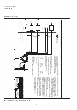
Level Plus Transmitter
FM16US0242X
MTS Systems Corporation
Sensors Division
3001 Sheldon Drive, Cary, N.C. 27513
EXPLOSION PROOF FOR CL. I, DIV. 1, GR. BCD T6...T3
CL. I, ZONE 0/1, AEx db IIB+H2 T6...T3 Ga/Gb
Ta = -40°C TO +71°C ; IP 65
INPUT: 28V (120mA) max
OUTPUT: 4-20mA
WARNING
: DO NOT OPEN WHEN AN EXPLOSIVE ATMOSPHERE
PRESENT FOR ZONE INSTALLATIONS, A SEAL SHALL BE INSTALLED WITHIN 50mm OF
THE ENCLOSURE. FOR DIVISION INSTALLATIONS A SEAL SHALL BE INSTALLED WITHIN 18 INCHES
OF THE ENCLOSUR
INSTALL PER # 651553-1/651597-1
MAX. PRESSURE 1000 PSI (RIGID SENSOR)
MAX. PRESSURE 435 PSI (FLEX SENSOR)
FM
US
APPROVED
P/N 551495-Rev B
R
!
Level Plus Transmitter
FM16US0242X
MTS Systems Corporation
Sensors Division
3001 Sheldon Drive, Cary, N.C. 27513
EXPLOSION PROOF FOR CL. I, DIV. 1, GR. ABCD T6...T3
CL. I, ZONE 0/1, AEx db IIB+H2 T6...T3 Ga/Gb
Ta = -40°C TO +71°C ; IP 65
INPUT: 28V (120mA) max
OUTPUT: 4-20mA
WARNING
: DO NOT OPEN WHEN AN EXPLOSIVE ATMOSPHERE
PRESENT FOR ZONE INSTALLATIONS, A SEAL SHALL BE INSTALLED WITHIN 50mm OF
THE ENCLOSURE. FOR DIVISION INSTALLATIONS A SEAL SHALL BE INSTALLED WITHIN 18 INCHES
OF THE ENCLOSUR
INSTALL PER # 651553-1/651597-1
MAX. PRESSURE 1000 PSI (RIGID SENSOR)
MAX. PRESSURE 435 PSI (FLEX SENSOR)
FM
US
APPROVED
P/N 551495-Rev B
R
!
13.3.2.2 Labels


