


Level Plus
®
Tank SLAYER
®
Operation Manual
I
10
I
Floats
Tank Slayer
®
transmitters offer numerous floats for different
applications such as stainless steel and Hastelloy
®
for both product
level and interface level. To be able to accurately detect the interface
level there needs to be a difference of at least 0.05 in specific gravities
between the product and interface liquids. For detailed information
about floats, refer to the ‘Accessories Catalog’, (MTS Part # 551103).
For assistance with selecting a specific float for your application,
please contact Technical Support with the following information:
• Specific gravity of liquid(s) being measured
• Process temperature
• Process opening size
• Vessel pressure
Tank Slayer
®
transmitters should be used with a float having an offset
weight and made of stainless steel or Hastelloy
®
C. This allows the
float to stay in contact with the pipe to prevent the buildup of an
electrostatic charge. For detailed information about floats, refer to the
‘Accessories Catalog’, (MTS Part #551103).
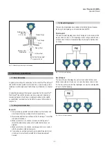
Internal electronics
All transmitters come with two electronic components of a sensing
element and a board set. Flexible sensing elements are standard on
Tank Slayer
®
. The board set consists of up to three electronic boards
and a display.
A temperature sensing function is optional with the Tank Slayer
®
transmitter. The temperature sensing device is a Digital Thermometer
mounted inside the transmitter’s outer pipe assembly. The Tank
Slayer
®
can be ordered with 1, 5, 12, or 16 temperature points.
Display
All LP-Series liquid level transmitters are shipped with a stylus (MTS
Part # 404108) to be used for manipulating the display. For single and
dual cavity housings, the stylus is designed to allow for programming
of the unit without removing the housing. When using the stylus make
sure to align the stylus with the shape outline around the buttons in
the same orientation. Failure to correctly align the stylus can cause the
display to not function properly. Password for entering the menu is
27513. For additional details consult the protocol specific Modbus
Interface Manual (MTS Part #551700), DDA Interface Manual (MTS
Part #551701), and HART
®
Interface Manual (MTS Part #551702).
Accessories
MTS also offers a series of displays, housings, converters, and
other accessories, please refer to the ‘Accessories Catalog’, (MTS
Part #551103).
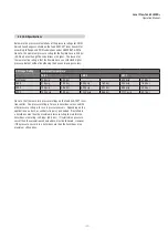
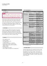
5.2 Accuracy
For magnetostrictive transmitters inherent accuracy is measured
in terms of non-linearity. Non-linearity is a measurement of any
imperfections in the waveguide that are reflected in the linearity of
the transmitter’s output. MTS tolerances reflect a maximum non-
linearity of ±1mm. MTS is able to achieve such strict tolerances by
manufacturing all of its own waveguide from a proprietary alloy and
testing 100% of all transmitters before shipping.
5.3 Warranty
Important:
Contact Technical Support or Customer Service for assistance if
you suspect that the transmitter is not working correctly. Technical
support can assist you with troubleshooting, part replacement, and
Returned Material Authorization (RMA) information if required.
All Level Plus
®
transmitters come with a two year limited warranty
from the factory shipment date. An additional extended warranty can
be purchased. A Return Materials Authorization (RMA) number is
required and must accompany any transmitter returns. Any unit that
was used in a process must be properly cleaned in accordance with
OSHA standards, before it is returned to the factory. A Material Safety
Data Sheet (MSDS) must also accompany the transmitter that was
used in any process.
5.4 Storage
If storage is required prior to installation, store indoors in a dry
environment at ambient temperature range not to exceed −40…+71°C
(−40…+160°F).
Fig. 6: Stylus (MTS Part # 404108)
Fig. 7: Display


