


Level Plus
®
Tank SLAYER
®
Operation Manual
I
15
I
6. Installation and mounting
6.1 Training
Warning:
When the pipe/hose of the LP-Series level transmitter is installed or
removed from the tank the release of flammable vapors will occur.
Take all necessary precaution when installing or removing the level
transmitter due to the release of flammable vapors.
Installation should only be conducted by qualified service personnel
according to IEC 60079-14 and local regulations or MTS trained
service technicians. MTS offers web based and in person training
for installation, commissioning, maintenance, and repair. MTS also
offers factory direct services for these same functions. Contact MTS to
discuss training or factory direct services before starting.
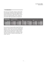
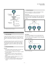
6.2 Stilling wells and guide poles
Level Plus
®
transmitters can be mounted in slotted or unslotted stilling
wells but a slotted stilling well is always preferred. Using a unslotted
stilling well will negatively affect performance of any level device as
the level in the stilling well can differ from the level in the tank. The
Level Plus
®
transmitter can also be installed to one side of the stilling
well to also allow for sampling and manual gauging from the same
opening as the automatic tank gauging. Contact technical support for
details.
Level Plus
®
transmitters do not require a stilling well for installation.
Our transmitters are installed in numerous tanks without stilling wells
with no loss in performance due to our patented flexible waveguide
and hose. A stilling well is highly recommended for agitated, turbulent,
and/or fast filling tanks.
6.3 Tools
• 9/16
"
Socket and ratchet
• Channel Lock pliers
• 3/16
"
Hex Key (Allen wrench)
• 1" Open End wrench
• Common head screwdriver, slotted screwdriver
6.4 Installation steps
Caution:
When assembling and installing the Tank Slayer
®
transmitter, be
careful not to allow the flexible hose to kink or be coiled in less
than 406.5 mm (16 in.) diameter. It is recommended that assembly
and mounting of this transmitter should not be done alone. To
ensure proper and safe assembly of the Tank Slayer
®
transmitter, a
minimum of two (2) individuals are recommended. Gloves are also
recommended. PPE may be required for work areas such as safety
shoes, safety glasses, hard hat, and fire resistant clothing.
1. Consult chapter 4.3 before starting.
2. Perform steps 1-10 in chapter 8.4.1 for Modbus or DDA. Perform
steps 1-9 in chapter 8.4.2 for Analog.
3. Remove the stop collar. With assistance, feed the flexible hose
through the hole of the removed tank flange until the flange
is positioned at the rigid section of pipe near the top of the
transmitter. Insert the threaded portion of the adjustable fitting
into the customer supplied flange and tighten (apply pipe thread
sealant if required). Be careful not to drop flange on the flexible
hose as damage may result.
4. Slide the product float onto the flexible hose. Slide the interface
float (optional) onto the flexible hose. Install stop collar 3 in.
from the bottom of rigid section (see ‘Note’ below). Do not
drop float(s) or allow them to free fall along the flexible hose as
damage may result.
NOTICE
The stop collar can be removed or adjusted based on the float
selected for the application. Please consult the factory for more
information.
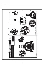
5. Mount the hook, weight, or the magnet to the welded end-plug
section of the pipe (this is the bottom rigid section of the pipe)
using the supplied nut, spacer and washer, tighten securely
as shown in Fig. 8, Fig. 11 and Fig. 9. For the magnet, remove
washer before installing in tank.
Fig. 8: Bottom fixing weight
Weight
Ø 5" (Ø 127 mm)
× 2" (51 mm) tall
Washer
Welded end-plug
Flexible hose
Float stop
collar
Spacer
Hexagon
nut


