


Matrix Series D Users Manual
Filter Description -continued
41
Part No.
INSTR-025 REL. 071207
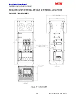
MTE BY-PASS option 010 , 011 and 013
Warning!!!
Equipment damage may result from activation of the bypass contactor during motor operation.
Ensure the motor is at rest before switching the bypass control contactor!
Purpose: Provide compatible hardware to integrate a system motor bypass when used in conjunction with
a drive which supports the bypass function as required for HVAC and control applications.
1.) To switch out the Matrix Filter® and connect utility power to the Matrix output terminals to
support a motor bypass initiated from the control contact of the drive.
2.) During the bypass mode, remove the effect of Matrix Filter® capacitor loading on drive utility
branch circuits
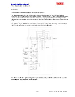
Design:
For low current Matrix Filter® s a single contactor CR1 provides the dual function switching to
accomplish bypassing the Matrix Filter® and removal of the filter’s capacitors. For higher current filters a
second powered contactor CR2 connects the capacitors to the filter circuit. See the schematic drawings
that shows these circuits.
Function description:
1.) (Matrix Filter® mode): The bypass coil CR1 is de-energized: the Matrix Filter® provides normal
harmonic attenuation of the VFD distorted power. For the dual contactor systems the capacitor
contactor CR2 must be powered to get maximum THID reduction.
2.) With 120 Vac 50 Hz on CR1 from the customer supplied contact selection:
A three phase connection is made across the Matrix Filter® input to the corresponding output
terminals. At the same time CR1 auxiliary contacts or the second CR2 contactor remove the
capacitors from the filter circuit.


