


Matrix Series D Users Manual
16
Part No.
INSTR-025 REL. 071207
INSTALLATION INSTRUCTIONS
Filter Installation
Matrix Filter®
are supplied in the following
mechanical configurations:
Panel mounted assemblies
Floor mounted general purpose NEMA 2,
& 3R cabinets,
Select a well ventilated, dust-free area away
from direct sunlight, rain or moisture. Do not
install in or near a corrosive environment.
Avoid locations where the filter would be
subjected to excessive vibrations.
Panel mounted filters are designed for
mounting in the vertical plane within the
customer’s enclosure. Panel mount units are
made up of a Harmonic Mitigating Reactor
(HMR) and one or more capacitor panel
assemblies referred to as cappanels on
drawings and diagrams.
The capacitor assembly should be located in
the lowest temperature regions of the
enclosure - generally toward the bottom and
away from high temperature components.
Mount the Harmonic Mitigating Reactor in a
location where the ambient temperature does
not exceed 50 degrees C. Allow a minimum
side clearance of four (4) inches and a
vertical clearance of six (6) inches for proper
heat dissipation and access.
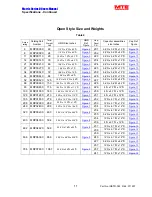
Figure 5 - 18 contain outline drawings for the
various ratings and show mounting orientation
with bolt patterns.
Include the power dissipation of the filter
along with all the other components located in
the enclosure to determine the internal
temperature rise and cooling requirements of
the enclosure.
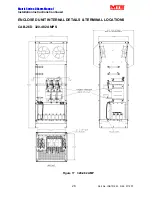
General purpose NEMA 2, and 3R enclosed
filters are designed for floor mounting in the
vertical plane in an environment suitable for
the enclosure type. Do not install in or near a
corrosive environment. Avoid locations where
the filter would be subjected to excessive
vibrations. Allow a minimum side and back
clearance of eight (8) inches and front
clearance of thirty-six (36) inches for proper
heat dissipation and access.
Refer to Article 430 Table 430.91 of the
National Electrical code for the selection of
the appropriate enclosure Type Number for
your application.


