background image

IR-DRYER2000.2 | IR-DRYER1000
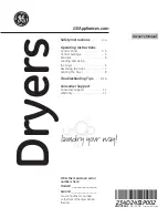
Device description

1. 

Emitters

2. 

Support post

3. 

Bottom support frame

4. 

Wheels

CONTROL PANEL DESCRIPTION

ON/OFF switch
TIMER – Time settings

OPERATING PRINCIPLE

1. 

Assemble the device in accordance with the diagram and position it correctly.

2. 

Then connect to power supply and turn on.

3. 

Use the knob to select the time foe which the device is to be active.

4. 

When not in use device off and disconnect it from the power source.

ON/OFF

TIMER

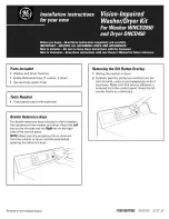
ASSEMBLING THE DEVICE

Assemble the device in accordance with the overview diagram below.

2

1

3

4

3

4

2

1

8

7

6
5
4

9

10

11

12

13

14

15

16

17

18

19

20

21

22

23

24

25

1

2

3

NUMBER

DESCRIPTION

1

Vertical support post

2

Upper cap

3

Plastic trim

4

Left clamp

5

Support frame

6

Terminal strip

7

IR unit

8

Plastic lever for adjusting angles

9

Connector

10

Right clamp

11

Handle

12

Bottom support rod

13

Top support rod

NUMBER

DESCRIPTION

14

Actuator

15

Actuator bracket

16

Front wheels

17

Support frame

18

Rear wheels
(with brake mechanism)

19

Flange

20

Cover

21

Control transformer

22

On/Off switch

23

Handle

24

Cover

25

Control panel

REPLACING LAMPS

1. 

Dismantle the IR unit

2. 

Remove the protective mesh

3. 

Remove  the  housing  from  both 

sides of the IR unit.

4. 

Remove  the  covers  from  both 

sides of the IR unit.

5. 

Then  remove  the  bulb  and  install


a new one with similar parameters.

6. 

Then assemble the IT unit and the device


in reverse order to dismantling.

TRANSPORTATION AND STORAGE

During transport, the machine should be protected from shaking, crashing and turning upside down. Store it 
in a properly ventilated place with dry air and without any corrosive gas.

Rev. 26.11.2018

Rev. 26.11.2018

12

13

Summary of Contents for IR-DRYER1000

Page 1: ...L USO MANUAL DE INSTRUCCIONES INSTRUKCJA OBS UGI N VOD K POU IT HASZN LATI TMUTAT I R D RY E R 3 0 0 0 2 I R D RY E R 3 0 0 0 1 I R D RY E R 2 0 0 0 1 I R D RY E R 2 0 0 0 2 I R D RY E R 1 0 0 0 Bedi...

Page 2: ...k nnen Verwenden Sie stets einen geerdeten Stromanschluss mit der richtigen Netzspannung siehe Anleitung oder Produktschild Sollten Sie bez glich des Anschlusses Zweifel haben lassen Sie ihn durch ei...

Page 3: ...llten Sie das Paket weiter transportieren halten Sie es aufrecht und stabil ENTSORGUNG DERVERPACKUNG Es wird darum gebeten das Verpackungsmaterial Pappe Plastikb nder und Styropor zu behalten um das G...

Page 4: ...es 1 Strahler 2 Stands ule 3 Unterer Rahmen 4 R der BESCHREIBUNG DER STEUERTAFEL ON OFF Schalter Ein Aus TIMER Zeiteinstellung FUNKTIONSPRINZIPIEN 1 Das Ger t ist entsprechend derVorlage zusammenzuset...

Page 5: ...ny risk of injury from fire or electric shock please follow the basic safety instructions when using this device Please read the instructions carefully and make sure that you have understood them well...

Page 6: ...the power source reflects the parameters on the rating plate Prior to first use remove and wash all elements and wash the entire machine Temperature depends on the distance between IR emitter and wor...

Page 7: ...frame 6 Terminal strip 7 IR unit 8 Plastic lever for adjusting angles 9 Connector 10 Right clamp 11 Handle 12 Bottom support rod 13 Top support rod NUMBER DESCRIPTION 14 Actuator 15 Actuator bracket...

Page 8: ...ji u ytkowania i upewnienie si e znale li Pa stwo odpowiedzi na wszystkie pytania dotycz ce tego urz dzenia Prosimy o staranne przechowywanie niniejszej instrukcji u ytkowania w pobli u produktu aby w...

Page 9: ...e w wyniku u ytkowania niezgodnego z przeznaczeniem ponosi u ytkownik PRZED PIERWSZYM U YCIEM W momencie otrzymania towaru nale y sprawdzi opakowanie pod k tem wyst powania ewentualnych uszkodze i otw...

Page 10: ...GRUNTUJ CY ANTYKOROZYJNY RUST PROOF PRIMER 8 Wyb r funkcji PODK AD POW OKA GRUNTUJ CA PRIMER 9 Wyb r funkcji POW OKA SZPACHLOWA WST PNA PRIMARY FILLER 10 Wyb r funkcji UTWARDZANIE POW OKI NAWIERZCHNIO...

Page 11: ...ekladem z n meck ho jazyka N VOD K OBSLUZE BEZPE NOSTN DOPORU EN Obecn bezpe nostn doporu en t kaj c se pou v n elektrick ch za zen Za elem minimalizace rizika razu v d sledku p soben ohn nebo razu e...

Page 12: ...kud bude balen op t p epravov no zajist te pros m aby bylo p epravov no ve vodorovn poloze a aby bylo ulo eno stabiln UTILIZACE OBALU Zachovejte pros m prvky obalu karton plastov p sky a polystyr n ab...

Page 13: ...i e 2 Sloupek 3 Spodn r m 4 Kole ka POPIS OVL DAC HO PANELU PRINCIP FUNKCE 1 Smontujte za zen podle obr zku a vhodn je um st te 2 Pak p ipojte nap jen a za zen zapn te 3 Pomoc voli e zvolte dobu po k...

Page 14: ...riques veuillez constamment prendre en consid ration les consignes et indications de s curit pr sentes dans ce manuel lorsque vous utilisez l appareil Veuillez lire attentivement ces instructions d em...

Page 15: ...s assurer qu aucun l ment ou composant du colis ne soit manquant Si l emballage est endommag prenez contact sous 3 jours avec la soci t de transport ainsi qu avec votre distributeur et fournissez un m...

Page 16: ...R 8 Choix de fonction APPLICATION DE LA PREMI RE COUCHE PRIMER 9 Choix de fonction PREMI RE COUCHE ENDUIT PRIMARY FILLER 10 Choix de fonction DURCIR LA COUCHE PROTECTRICE TOP COAT 11 Choix de fonction...

Page 17: ...tilizzo di apparecchi elettrici Per minimizzare il rischio di ustioni o folgorazioni rispettare rigorosamente le norme di sicurezza Leggere attentamente le istruzioni d uso e assicurarsi di aver compr...

Page 18: ...alora il pacco dovesse essere ulteriormente trasportato assicurarsi di mantenerlo dritto e stabile SMALTIMENTO DELL IMBALLAGGIO Conservare l imballaggio cartone bande di plastica e polistirolo per pro...

Page 19: ...locare il dispositivo come indicato 2 Allacciare il dispositivo alla corrente e accenderlo 3 Impostare la durata con i tasti 4 Alla fine dei lavori spegnere il dispositivo e scollegarlo dalla corrente...

Page 20: ...e dispositivos el ctricos Para reducir el riesgo de lesiones por quemadura o electrocuci n le rogamos que tome siempre ciertas medidas de seguridad cuando utilice este aparato Lea con detenimiento est...

Page 21: ...reparaci n MONTAJE DE LA M QUINA UBICACI N DEL EQUIPO DEL EQUIPO Coloque el aparato en posici n vertical sobre una superficie seca y resistente que no se deforme durante el funcionamiento Esta superf...

Page 22: ...L DE CONTROL PRINCIPIOS DE FUNCIONAMIENTO 1 El equipo se debe de montar y colocar seg n el esquema a continuaci n 2 Enchufe el equipo al suministro el ctrico y enci ndalo 3 Ajuste el tiempo por medio...

Page 23: ...ben k rj k hogy a k sz l k haszn latakor tartsa be az alapvet biztons gi vint zked seket K rj k olvassa el figyelmesen az tmutat t s gy z djen meg r la hogy nem maradt k rd se a term k haszn lat ra v...

Page 24: ...nyek k z tt se nyissa fel a term k h z t 12 Ne n zzen a bekapcsolt sug rz ba 13 A k sz l k nagyon magas h m rs kletekre melegszik fel A munka befejez se ut n a k sz l k egy ideig meleg marad Ne rintse...

Page 25: ...s kletszab lyz kkal vannak felszerelve Az IR DRYER3000 1 eset n a h m rs kletet a gombokkal lehet be ll tani az IR DRYER2000 1 eset n a pedig a funkci gombokkal 5 Ezut n v lassza ki a haszn lni k v nt...

Page 26: ...ifizieren und Reparieren durch unqualifizierte Personen verboten 3 Den Hebel ziehen um die Position der Lampen einzustellen 4 Der Hebel hat eine hydraulische Unterst tzung ACHTUNG DAS GER T NICHTVERWE...

Page 27: ...de 16A 3 Requiere una conexi n de 16A 4 Voltaje y frecuencia de red deben corresponderse con los indicados en la placa de caracter sticas t cnicas 5 Garantizar un buen estado de la conexi n a la red e...

Page 28: ...la obvykle 30 50 cm Po ukon en pr ce se za zen m nastavit lampy v nejvy horn pozici POZOR HORK POVRCH Nedot kat se Toto za zen je b hem pr ce etr mn hork POZOR 1 Ubezpe te se e typ proudu a nap t odpo...

Page 29: ...Verf gung stehenden M glichkeiten der R ckgabe oder Sammlung von Altger ten 1 RICHTLINIE 2002 96 EG DES EUROP ISCHEN PARLAMENTS UND DES RATES BER ELEKTRO UND ELEKTRONIK ALTGER TE 2 Gesetz ber das Inve...

Reviews: