


QM7500 Technical Manual
QM31930/03093 Rev AD
Servicing 15
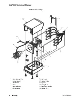
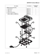
Replacing the Valve/Photocell Board
Removing the Valve/Photocell Board
1) Prepare your QM7500 for servicing. (See page 6.)
2) Remove the printhead cover by removing the three screws from the bottom of
the printhead. With the unit flat on the workbench, place your thumb on the
regulator and press down lightly as you lift up the top half of the printhead.
Note: Hold the components in place with your finger if necessary. Make
sure the valve/photocell board assembly remains in the printhead base.
Also, avoid unnecessary flexing of the cable between the two boards to
prevent damaging the cable connections.
3) Carefully lift the controller mounting frame off the bottom half of the
printhead.
4) Carefully pull the tubing off the regulator ports.
Note: Over time the tubing end may stretch. You must trim the tubing to
ensure a snug fit on the new regulator ports or you may need to replace
the tubing.
5) Pull the tubing (all of it) through the opening in the valve board.
6) Disconnect the IDC connector from the valve board.
7) Remove the regulator.
8) Slide out the nozzle block; leave the valves connected to the nozzle block.
9) Slide out the valve/photocell board assembly.
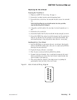
10) Remove the valve retaining clip.
11) Disconnect the valves from the old valve board taking care not to bend or
break valve leads.


