USER MANUAL
MTU AIS-C
Page 39
R
v0
1
9.1.
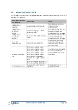
MESSAGE DATA MAPPING #6
The message field data source mapping #6 is shown in the table below according to the GLA
standard for message 6.
Message #6 data field
DAC 235, Fl 10
Data source
Notes
Analog voltage
(internal)
Supply voltage to transponder
No additional connection is
required for this
measurement
Analog voltage
(external 1)
ISO AN1
Isolated analog input 1 of the
Sensor Interface
Note that the default scaling
values for this ADC are
configured for this message.
Analog voltage
(external 2)
ISO AN2
Sensor Interface isolated analog
input 2
Note that the default scaling
values for this ADC are
configured for this message.
Status bits
(internal, 5-bit)
Light state bits and RACON.
These values will also be
used in the message #21
when the sensor is used as a
state bit source.
State bits (external, 8
bits)
Bit 0 - Isolated digital input 1
Bit 1 - Isolated digital input 2
Bit 2 - Isolated digital input 3
Bit 3 - Isolated digital input 4
Bit 4 - Isolated digital input 5
Bit 5
–
Set to 1 if the current
detection of the light >-100mA,
but 0
Bit 6 - Non-isolated digital input 1
Bit 7 - Non-isolated digital input 2
The light current sensing bit
5 can be used with the
internal ISENSE loop or ISO
AN2 input
Out-of-position status
Transponder's out-of-position
algorithm
Transponder's out-of-
position algorithm

