MSI MS - 9211 User Manual Download Page 36

2-6

 MS-9211 1U Rackmount Server

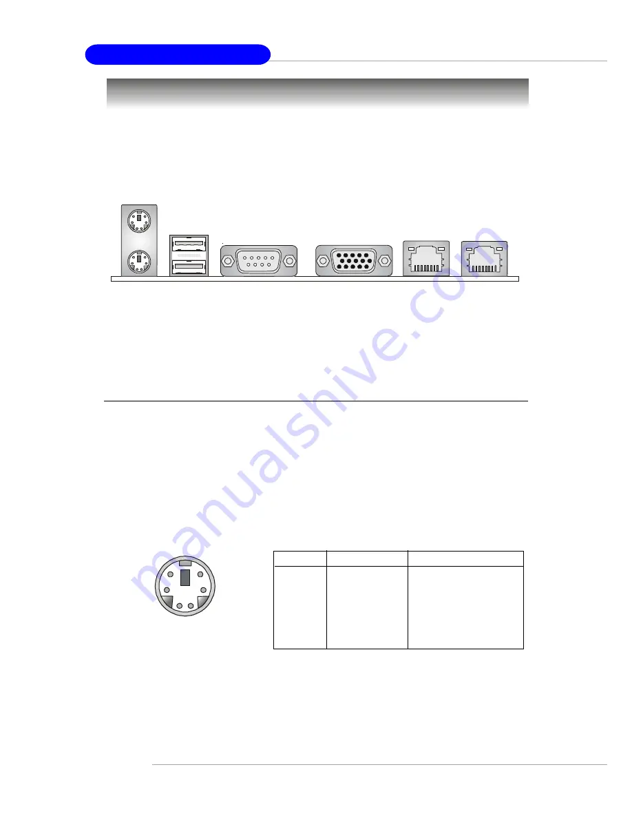
The back panel provides the following connectors:

Back Panel

Mouse Connector

The mainboard provides a standard PS/2

®

 mouse mini DIN connector

for attaching a PS/2

®

 mouse.  You can plug a PS/2

®

 mouse directly into this

connector.  The connector location and pin assignments are as follows:

PIN

SIGNAL

DESCRIPTION

1

Mouse DATA

Mouse DATA

2

NC

No connection

3

GND

Ground

4

VCC

+5V

5

Mouse Clock

Mouse clock

6

NC

No connection

 Pin Definition

PS/2 Mouse (6-pin Female)

2

1

3

4

5

6

Mouse

Keyboard

USB

COM 1

VGA

LAN

LAN

Summary of Contents for MS - 9211

Page 1: ...1U Rackmount Server MS 9211 User s Guide Version 1 0 G52 S9211X1...

Page 2: ...with the instruction manual may cause harmful interference to radio communications Operation of this equipment in a residential area is likely to cause harmful interference in which case the user wil...

Page 3: ...iness Machines Corporation Microsoft is a registered trademark of Microsoft Corporation Windows 98 2000 NT XP are registered trademarks of Microsoft Corporation Netware is a registered trademark of No...

Page 4: ...module 9 All cautions and warnings on the equipment should be noted 10 Never pour any liquid into the opening that could damage or cause electri cal shock 11 If any of the following situations arises...

Page 5: ...1 5 D LED optional 1 6 LCD Front Panel Control 1 8 System Configuration 1 18 FrontView 1 18 RearView 1 20 TopView 1 21 Packing Checklist 1 22 Chapter2 HardwareSetup 2 1 Central Processing Unit CPU 2...

Page 6: ...2 14 Front USB Connectors JUSB2 JUSB3 2 15 IrDA Infrared Module Header IR2 2 17 Event Input Connector J14 2 17 LAN LED Connectors JACT1 JACT2 2 18 LCD Panel Connector JLCD1 2 18 DiagnosticLEDs LED1 LE...

Page 7: ...e Control 3 27 Load Fail Safe Optimized Defaults 3 28 Set Supervisor User Password 3 29 Chapter 4 Chassis Installation 4 1 System Assembly Flowchart 4 2 System Assembly 4 4 Chassis Cover 4 4 CPU Heats...

Page 8: ...ngratulations on your purchase of the MS 9211 1U Rackmount Server This high performance barebone system supports the powerful Intel Pentium 4 processor and the industry leading hardwares and provides...

Page 9: ...Supports four memory banks using two 184 pin DDR DIMMs hSupports up to 2GB PC2100 PC1600 DDR SDRAMs h Supports 2 5v DDR SDRAM Slots h One 32 bit Master PCI bus slot support 3 3v 5v PCI bus interface O...

Page 10: ...t pins Interfaces with the host via a slave SMBus interface it interfaces with the LAN On Motherboard LOM and with peripherals via two independent master SMBus interfaces BIOS h The mainboard BIOS pro...

Page 11: ...Supply JFP1 JLCD1 IR2 JACT2 JACT1 J14 FWH ATI RageXL Intel LAN Chip PCI 1 IDE 4 IDE 3 Promise PDC20276 Winbond PC87431HM Winbond W83627HF AW USB ports JPW1 LAN 1 LAN 2 Top mouse Bottom keyboard JBAT1...

Page 12: ...eratures monitor fan speed s monitor system voltage monitor chassis intrusion If one of the items above is abnormal the program main screen will be immediately shown on the screen with the abnormal it...

Page 13: ...users can use the feature to detect if there are any problems or failures The definitions of LED signal combinations are listed below D LED Description System Power ON The D LED will hang here if the...

Page 14: ...ter BIOS Sign On This will start showing information about logo processor brand name etc Testing Base and Extended Memory Testing base memory from 240K to 640K and extended memory above 1MB using vari...

Page 15: ...talling the LCD Control Service Version V2 2 OS supported Windows NT 4 with Service Pack 4 or latest version Windows 2000 Windows XP Step 1 Insert the installation CD into the CD ROM drive Browse to t...

Page 16: ...ting Started Step 4 Setup has finished installing the LCD Control service on your computer Click Install service to enable the LCD Control service Step 5 Click OK to continue You can restart the compu...

Page 17: ...nt to Programs Under Programs Click LCD Control Panel and the following screen will pop up Click Remove service to disable the LCD Control service Step 3 Under Control Panel click Add Remove Programs...

Page 18: ...unction Menu After you have installed the LCD Control Panel Service you can simply use the LCD Front Panel Control buttons to get access to the information under LCD Info H W Monitor and System Conf m...

Page 19: ...isk Information LAN1 LAN2 Restart OS Shutdown OS Set Date Set Time IP Net Mask Set IP Set Net Mask IP Net Mask Set IP Set Net Mask Yes No Yes No Disk C Disk D Disk E Disk F Size Usage Available Size U...

Page 20: ...Msg CPU Init BIOS POST 2B If the system has VGA issues it will stop at 2B Msg VGA Init BIOS POST 2D It shows information about logo processor brand name Msg Sign on Msg BIOS POST 52 If the system has...

Page 21: ...1 5 Show LCD Firmware version V1 1 Mode 2 5 Show LCD working mode Communication Build date 3 5 Show LCD Firmware build date 2002 03 25 Baud Rate 4 5 Show LCD communication speed with COM port 9600 For...

Page 22: ...RPM V core 6 15 Show V core voltage information 1 46V I O Voltage 7 15 Show I O voltage information 1 08V 3 3V 8 15 Show 3 3V voltage information 3 26V 5V 9 15 Show 5V voltage information 5 07V 12V 1...

Page 23: ...Unable to show available memory size 358MB Hard Disk 5 9 It can detect 4 disks on this system Information Disk C 1 4 Size 1 3 Show this partition s size 3698MB 3698MB Usage 2 3 Unable to show the use...

Page 24: ...Mask information 255 255 255 0 Set IP Allow users to set the system s IP 000 000 000 000 Setmask Allow users to set the system s Net Mask 000 000 000 000 LAN2 7 9 IP 1 4 Show the system IP informatio...

Page 25: ...figuration of the MS 9211 from different angles and the connectors and buttons on the front and back panel 1 LCD Front Panel 2 SlimCD ROMDrive optional 3 LED Indicators 4 Power Button 5 USB Ports 6 LC...

Page 26: ...sed to turn on or off the system PowerIndicator This indicator shows the power status of the system It glows when the main power is turned on LANStatusIndicators These two LED indicators flash to show...

Page 27: ...Rackmount Server Rear View 1 Power Connector 2 Heat Dissipation Opening 3 PS 2 Keyboard Connector 4 PS 2 Mouse Connector 5 Serial Port COM A 6 VGAPort 7 LAN Jacks 1 2 8 USB Ports 1 2 1 2 after enlarge...

Page 28: ...1 21 Getting Started TopView 1 ATX Power Supply 2 SlimCD ROMDrive optional 3 DIMM Slots 4 Riser Card Bracket 5 CPU Socket 6 Blower 7 AC Power Connector 7 6 1 2 3 5 4...

Page 29: ...s listed below are present If any item contained in the package is damaged or missing please contact your local dealer for replacement In addition keep the box and packing materials for possible futur...

Page 30: ...1 23 Getting Started Chassis Rail Bracket Set M5x12 screws x2 M4x6 black screws x4 EarSet M4x6 screws x8 M4 Nut x8 M5x8 screws x8 2 ears 4 brackets 4 secure plates Rail Set 2 rails M4x4 screws x8...

Page 31: ...up procedures While doing the installation be careful in holding the components and follow the installation procedures For some components if you install in the wrong orientation the components will n...

Page 32: ...locking This motherboard is designed to support overclocking However please make sure your components are able to toler ate such abnormal setting while doing overclocking Any at tempt to operate beyon...

Page 33: ...s DIMM 1 2 Memory DDR DIMM Slots DIMM 1 2 Introduction to DDR SDRAM DDR Double Data Rate SDRAM is similar to conventional SDRAM but doubles the rate by transferring data twice per cycle It uses 2 5 vo...

Page 34: ...d on the slots in any order You can install either single or double sided modules to meet your own needs Memory modules can be installed in any combination as follows S Single Side D Double Side Slot...

Page 35: ...e ATX power supply make sure the plug of the power supply is inserted in the proper orientation and the pins are aligned Then push down the power supply firmly into the connector ATX 12V Power Connect...

Page 36: ...ector for attaching a PS 2 mouse You can plug a PS 2 mouse directly into this connector The connector location and pin assignments are as follows PIN SIGNAL DESCRIPTION 1 Mouse DATA Mouse DATA 2 NC No...

Page 37: ...n Definition PS 2 Keyboard 6 pin Female 2 1 3 4 5 6 USB Connectors The mainboard provides a UHCI Universal Host Controller Interface Universal Serial Bus root for attaching USB devices such as keyboar...

Page 38: ...tion Serial Port Connectors COM 1 COM2 The mainboard offers two 9 pin connectors as serial port COM 1 COM 2 The ports are 16550A high speed communication ports that send receive 16 bytes FIFOs You can...

Page 39: ...ps You can con nect a network cable to either LAN jack 10 100 LAN Pin Definition PIN SIGNAL DESCRIPTION 1 TDP Transmit Differential Pair 2 TDN Transmit Differential Pair 3 RDP Receive Differential Pai...

Page 40: ...provides connectors to connect to FDD IDE HDD case modem LAN USB Ports IR module and CPU System Power Supply FAN Floppy Disk Drive Connector FDD1 The mainboard provides a standard floppy disk drive co...

Page 41: ...sk cable IDE1 Primary IDE Connector The first hard drive should always be connected to IDE1 IDE1 can connect a Master and a Slave drive You must configure second hard drive to Slave mode by setting th...

Page 42: ...ompatible with the existing Ultra ATA interface The low cost RAID Redundant Array of Independent Disks solution integrates two IDE RAID connectors that support PIO mode 0 4 Bus Master and Ultra DMA 33...

Page 43: ...ng the wire to the connectors always take note that the red wire is the positive and should be connected to the 12V the black wire is Ground and should be connected to GND If the mainboard has a Syste...

Page 44: ...Guide 1 2 9 10 JFP1 HDD LED Reset Switch Power LED Power Switch PIN SIGNAL DESCRIPTION 1 HD_LED_P Hard disk LED pull up 2 FP PWR SLP MSG LED pull up 3 HD_LED_N Hard disk active LED 4 FP PWR SLP MSG L...

Page 45: ...Guide USB 2 0 technology increases data transfer rate up to a maximum throughput of 480Mbps which is 40 times faster than USB 1 1 and is ideal for connecting high speed USB interface peripherals such...

Page 46: ...3 pin headers separately 4 Place the USB 2 0 bracket into the appropriate slot of the system case USB 2 0 Bracket optional MSI Reminds You The USB 2 0 controller is backwards compatible with USB 1 1 s...

Page 47: ...in Signal 1 NC 2 NC 3 VCC5 4 GND 5 IRTX 6 IRRX Pin Definition Intel 845 chipset Event Input Connector J14 This connector is used to link the Event Input Button to facililtate the management of the rem...

Page 48: ...JACT2 is for LAN2 jack Both LAN1 LAN2 jacks are located on the back panel LCD Panel Connector JLCD1 The connector is additionally provided for connection to a LCD panel which shows information on the...

Page 49: ...arious combinations of LED signals For defini tions of 16 signal combinations please refer to D LED in Chapter 1 Intel 845 chipset LED4 LED3 LED2 LED1 Intel 845 chipset Server Management LEDs LED5 LED...

Page 50: ...to keep the data of system configuration With the CMOS RAM the system can automatically boot OS every time it is turned on If you want to clear the system configuration use the JBAT1 Clear CMOS Jumper...

Page 51: ...omponent Interconnect Slot The PCI slot allows you to insert the expansion card to meet your needs When adding or removing the expansion card make sure that you unplug the power supply first Meanwhile...

Page 52: ...tup pro gram and allows you to configure the system for optimum use You may need to run the Setup program when An error message appears on the screen during the system booting up and requests you to r...

Page 53: ...essing Ctrl Alt and Delete keys Move to the previous item Move to the next item Move to the item in the left hand Move to the item in the right hand Enter Select the item Esc Jumps to the Exit menu or...

Page 54: ...n use arrow keys to highlight the field and press Enter to call up the sub menu Then you can use the control keys to enter values and move from field to field within a sub menu If you want to return t...

Page 55: ...enu to configure the special enhanced features Advanced Chipset Features Use this menu to change the values in the chipset registers and optimize your system s performance Integrated Peripherals Use t...

Page 56: ...this menu to specify your settings for frequency voltage control Load Fail Safe Defaults Use this menu to load the BIOS default values for minimal but stable system performance Load Optimized Default...

Page 57: ...at is day month date year day Day of the week from Sun to Sat determined by BIOS Read only month The month from Jan through Dec date The date from 1 to 31 can be keyed by numeric function keys year Th...

Page 58: ...g Zone Cylinder location of the landing zone Sector Number of sectors Drive A B This item allows you to set the type of floppy drives installed Available options are None 360K 5 25 in 1 2M 5 25 in 720...

Page 59: ...POST error or initial messages to the BMC Event log If you don t want to store POST error or initial messages to the DMI Event log select Disabled When Cleared is selected the BMC event log will be cl...

Page 60: ...of the Watchdog Timer No Action Hard Reset Power Down Power Cycle WatchDog Timer Counter This feature allows users to set the time interval to reboot the computer if a timeout event occurs Setting op...

Page 61: ...ttempt to write data into this area is made BIOS will display a warning message on screen and beep Set ting options Disabled Enabled BIOS Flash Write Control This function protects the BIOS from accid...

Page 62: ...a platform can support improve reaction and response time and increase number of transaction that can be executed Setting options Enabled Disabled Quick Power On Self Test The option speeds up Power O...

Page 63: ...e Num Lock key when the system is powered on Setting to Off will allow users to use the arrow keys on the numeric keypad Setting options On Off Gate A20 Option This item is to set the Gate A20 status...

Page 64: ...ation version to be used for the operating system You need to select the MPS ver sion supported by your operating system To find out which version to use consult the vendor of your operating system Se...

Page 65: ...ent After Boot This setting determines whether or not to keep terminals console redirection running after the OS has booted Setting options Disabled Enabled Report No FDD For WIN 95 For compatibility...

Page 66: ...atency Time This controls the timing delay in clock cycles before SDRAM starts a read command after receiving it Settings 1 5 2 2 5 3 clocks 1 5 clocks increases the system performance the most while...

Page 67: ...Memory Frequency For Use this item to configure the clock frequency of the installed SDRAM Set ting options Auto PC100 PC133 DRAM Read Thermal Mgmt This setting is used to activate the thermal manage...

Page 68: ...tion is underway Select Enabled to support compliance with PCI specification ver sion 2 1 Setting options Enabled Disabled Delay Prior to Thermal When the CPU temperature reaches a factory preset leve...

Page 69: ...rface supports Modes 0 4 provide increased performance In Auto mode BIOS automatically de termines the best mode for each IDE device IDE Primary Secondary Master Slave UDMA Ultra DMA implementation is...

Page 70: ...also called block transfer multiple commands or multiple sector read write Enabled enables IDE con troller to use block mode Disabled allows the controller to use standard mode Onboard LAN1 LAN2 Boot...

Page 71: ...is allowed Under Half Duplex mode only asynchronous bi directional transmission reception is allowed Use IR Pins Please consult your IR peripheral documentation to select the correct setting of the T...

Page 72: ...normal operation of the computer i e memory parity check Setting options Enabled Disabled Power Management This item is used to select the degree or type of power saving and is related to these modes...

Page 73: ...f system activity is not detected for the length of time specified in this field all devices except CPU will be shut off Settings are Disabled 1 Min 2 Min 4 Min 8 Min 12 Min 20 Min 30 Min 40 Min and 1...

Page 74: ...ings 0 31 Time hh mm ss Alarm The field specifies the time for Resume by Alarm Format is hour minute second Reload Global Timer Events Primary IDE 0 1 Secondary IDE 0 1 FDD COM LPT Port PCI PIRQ A D G...

Page 75: ...d Disabled Select Enabled to reset Extended System Configuration Data ESCD when you exit Setup if you have installed a new add on card and the system reconfiguration has caused such a serious conflict...

Page 76: ...n handle data from the CPU on each set of palette registers on every video device Bit 5 of the command register in the PCI device configuration space is the VGA Palette Snoop bit 0 is disabled For exa...

Page 77: ...ches the upper limit preset in this setting the warn ing mechanism will be activated This helps you to prevent the CPU overheat problem Current System CPU Temperature System Power CPU Fan Vcore V 1 8...

Page 78: ...d Spread Spectrum When the motherboard s clock generator pulses the extreme values spikes of the pulses creates EMI Electromagnetic Interference The Spread Spec trum function reduces the EMI generated...

Page 79: ...ore all of the BIOS settings to the default Fail Safe or Optimized values The Optimized Defaults are the default values set by the mainboard manufacturer specifically for op timal performance of the m...

Page 80: ...en a password has been set you will be prompted to enter it every time you try to enter Setup This prevents an unauthorized person from chang ing any part of your system configuration Additionally whe...

Page 81: ...nt of the MS 9211 Rack Mounting describes the procedures for mounting the unit into the rack in details You can use the system assembly flowchart and the chart below to determine the proper sequence f...

Page 82: ...note that always wear anti static gloves when handling electrical components and exercise caution during the installation process For more information contact your local dealer or experienced technici...

Page 83: ...hassis Installation FINISH REMOVE RISER CARD BRACKET CONNECT HDD FDD CD ROM CABLES POWER CORDS INSTALL RISER CARD REPLACE RISER CARD BRACKET CHECK IF ALL PARTS ARE PROPERLY CONNECTED REPLACE CHASSIS C...

Page 84: ...e release buttons and then push the cover backward to lift it up Chassis Cover WARNING Before you remove or install these modules make sure the server is not turned on or connected to the AC power To...

Page 85: ...PU Heatsink and Fan Duct Place the CPU on top of the socket with the gold arrow pointing to the lever gold arrow Push the lever down to secure the CPU in place 3 4 Locate the CPU socket and lift the l...

Page 86: ...socket Position the PHP122 heatsink onto the heatsink socket carefully to avoid damaging the components around CPU Heatsink and Fan Duct continued Locate the four screw holes of the PHP122 heatsink Sc...

Page 87: ...4 7 Chassis Installation Replace the fan duct to ensure proper heat dissipation Plug in the power cord of the PHP122 heatsink You have finished installing the heatsink and fan duct 6 7 8 9 10...

Page 88: ...4 8 MS 9211 1U Rackmount Server Insert the SDRAM module into the DIMM slot The plastic clip at each side of the DIMM slot will automati cally close DIMM Locate the DIMM slots on the mainboard 1 2...

Page 89: ...tallation Unscrew the HDD cover plate Turn over the HDD cover plate Hard Disk Drives Remove the right bracket 1 Place the first hard disk drive into the chassis and make sure the cables are properly c...

Page 90: ...1 1U Rackmount Server Replace the right bracket Follow the same procedures to install the second hard disk drive Hard Disk Drives continued Replace the HDD cover plate 5 6 7 Screw the HDD cover plate...

Page 91: ...on Remove the riser card bracket Unscrew the I O shield from the riser card bracket Save the screw for later use Riser Card Screw the SCSI card firmly to the riser card bracket 1 2 3 4 Insert the SCSI...

Page 92: ...4 12 MS 9211 1U Rackmount Server Replace the riser card bracket 5...

Page 93: ...ew the side rails to both sides of the chassis Chassis Rails and Ears M4x6 black M4x6 1 2 TIPS Attach the brackets front and rear onto the rails the position of the rear bracket should be adjustable w...

Page 94: ...h the screws M5x8 Align the chassis rails with the rack rails and then push the system into the rack fully Note The chassis rails must match the rack rails well and the ball bearing set of the rack ra...

Page 95: ...ve the system from the rack To slide the system into the rack first align the chassis rails with the rack rails Then simultaneously press the locking tabs on both sides of the chassis rails and slide...

Reviews: