background image

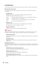
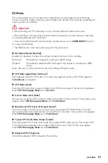
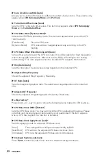
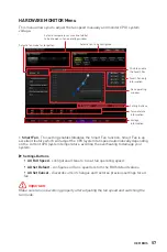
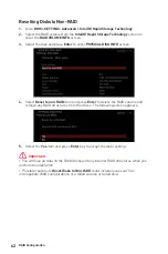
Resetting Disks to Non-RAID

1. 

Go to 

BIOS > SETTING > Advanced > Intel(R) Rapid Storage Technology

.

2. 

Select the RAID volume from the 

Intel(R) Rapid Storage Technology

 screen to 

enter the 

RAID VOLUME INFO

 screen.

3. 

Select the disk and press 

Enter

 to enter 

PHYSICAL DISK INFO

 screen.

4. 

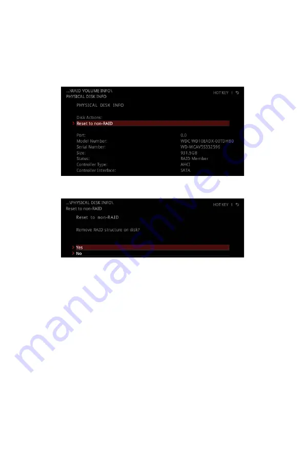
Select 

Reset to non-RAID

 item and press 

Enter

 to delete the RAID volume and 

remove any RAID structures from the drives. The following screen appears:

5. 

Select the 

Yes

 item and press 

Enter

 key to accept the disk reseting.


Important


You will lose all data on the RAID drives and any internal RAID structures when you 

perform this operation.


Possible reasons to 

Reset Disks to Non-RAID

 could include issues such as 

incompatible RAID configurations or a failed volume or failed disk.

62

RAID Configuration

Summary of Contents for MAG B460M BAZOOKA

Page 1: ...the installations also provide video demonstrations Please link to the URL to watch it with the web browser on your phone or tablet You may have even link to the URL by scanning the QR code Preparing Tools and Components Intel LGA 1200 CPU CPU Fan DDR4 Memory Graphics Card SATA Hard Disk Drive SATA DVD Drive Phillips Screwdriver Chassis Power Supply Unit A Package of Screws Thermal Paste ...

Page 2: ...he computer before installation is completed This could cause permanent damage to the components as well as injury to the user If you need help during any installation step please consult a certified computer technician Always turn off the power supply and unplug the power cord from the power outlet before installing or removing any computer component Keep this user guide for future reference Keep...

Page 3: ...3 Safety Information Installing a Processor https youtu be 4ce91YC3Oww 1 2 3 6 4 5 7 8 9 ...

Page 4: ...4 Safety Information Installing DDR4 memory http youtu be T03aDrJPyQs DIMMA2 DIMMA2 DIMMB2 DIMMA1 DIMMA2 DIMMB1 DIMMB2 ...

Page 5: ...D HDD LED HDD LED POWER LED POWER LED POWER LED 1 2 10 9 Power LED HDD LED Reset Switch Reserved Power Switch JFP1 1 HDD LED 2 Power LED 3 HDD LED 4 Power LED 5 Reset Switch 6 Power Switch 7 Reset Switch 8 Power Switch 9 Reserved 10 No Pin R E S E T S W P O W E R S W P O W E R L E D P O W E R L E D H D D L E D ...

Page 6: ...6 Safety Information Installing the Motherboard 3 https youtu be wWI6Qt51Wnc Torque 3 kgf cm 3 kgf cm 0 3 N m 2 6 lbf in 2 1 ...

Page 7: ...7 Safety Information Connecting the Power Connectors http youtu be gkDYyR_83I4 ATX_PWR1 CPU_PWR1 ...

Page 8: ...8 Safety Information Installing SATA Drives http youtu be RZsMpqxythc 1 2 3 4 5 ...

Page 9: ...9 Safety Information 1 Installing a Graphics Card http youtu be mG0GZpr9w_A 2 3 4 5 6 ...

Page 10: ...10 Safety Information Connecting Peripheral Devices ...

Page 11: ...11 Safety Information Power On 4 3 1 2 ...

Page 12: ...able 20 Realtek Audio Console 20 Overview of Components 22 CPU Socket 24 DIMM Slots 25 PCI_E1 3 PCIe Expansion Slots 26 SATA1 4 SATA 6Gb s Connectors 26 M2_1 2 M 2 Slots Key M 27 JFP1 JFP2 Front Panel Connectors 29 JCOM1 Serial Port Connector 29 CPU_PWR1 ATX_PWR1 Power Connectors 30 JAUD1 Front Audio Connector 31 JUSB1 2 USB 2 0 Connectors 31 JUSB3 USB 3 2 Gen 1 Connector 32 JTPM1 TPM Module Conne...

Page 13: ... 48 OC Menu 51 M FLASH Menu 55 OC PROFILE Menu 56 HARDWARE MONITOR Menu 57 RAID Configuration 59 Enabling Intel Rapid Storage Technology 59 Creating RAID Volume 60 Removing a RAID Volume 61 Resetting Disks to Non RAID 62 Rebuilding RAID Array 63 Installing RAID Driver 64 Installing Intel Rapid Storage Technology Software 64 Intel Optane Memory Configuration 65 System Requirements 65 Installing the...

Page 14: ...t from CPU 2x PCIe x1 slots from PCH Onboard Graphics 1x HDMI port supporting a maximum resolution of 4096x2160 30Hz 2560x1600 60Hz 1x DVI D port supports a maximum resolution of 1920x1200 60Hz Storage Intel B460 Chipset 4x SATA 6Gb s ports 2x M 2 slots Key M M2_1 supports up to PCIe 3 0 x4 and SATA 6Gb s 2242 2260 2280 22110 storage devices M2_2 supports up to PCIe 3 0 x4 2242 2260 2280 storage d...

Page 15: ...2 Gen 1 5Gbps Type A ports 1x LAN RJ45 port 3x audio jacks Internal Connectors 1x 24 pin ATX main power connector 1x 8 pin ATX 12V power connector 4x SATA 6Gb s connectors 1x USB 3 2 Gen 1 5Gbps connector support additional 2 USB 3 2 Gen 1 5Gbps ports 2x USB 2 0 connectors support additional 4 USB 2 0 ports 1x 4 pin CPU fan connector 1x 4 pin water pump connector 2x 4 pin system fan connectors 1x ...

Page 16: ... 128 Mb flash UEFI AMI BIOS ACPI 6 2 SM BIOS 3 2 Multi language Software Drivers DRAGON CENTER Intel Extreme Tuning Utility CPU Z MSI GAMING Google Chrome Google Toolbar Google Drive Norton Internet Security Solution Dragon Center Features LAN Manager Mystic Light User Scenario Monitor Hardware Monitor True Color Live Update DPC Latency tuner Speed Up Smart Tool Super Charger Please refer to http ...

Page 17: ...es Audio Audio Boost Storage Turbo M 2 Intel Optane Memory Ready Fan Smart Fan Control LED Mystic Light Mystic Light Extension RGB Mystic Light Extension RAINBOW Mystic light SYNC EZ DEBUG LED Protection PCI E Steel Armor Performance DDR4 Boost GAME Boost X Boost ...

Page 18: ...B460M BAZOOKA Documentation User manual 1 Case stand off notification 1 Quick installation guide 1 Application Driver DVD 1 Cables SATA 6G cables 2 cables pack 1 Accessories Case badge 1 Product registration card 1 M 2 screws 3 pcs pack 1 Important If any of the above items are damaged or missing please contact your retailer ...

Page 19: ... Block Diagram 6x USB 2 0 2 Channel DDR4 Memory DMI 3 0 PCH Processor NUVOTON 6687 Realtek ALC892 6x USB 3 2 Gen 1 2x PCIe x1 slots Realtek LAN RTL8111H Rear Audio Jacks 1x M 2 1x M 2 1x SATA 6Gb s Switch 3x SATA 6Gb s ...

Page 20: ...ow Linked Blinking Data activity Speed LED Status Description Off 10 Mbps connection Green 100 Mbps connection Orange 1 Gbps connection LAN Port LED Status Table Realtek Audio Console After Realtek Audio Console is installed You can use it to change sound settings to get better sound experience Jack Status Connector Settings Device Selection Main Volume Application Enhancement ...

Page 21: ...nfigures the connection settings Audio 7 1 channel Configuration To configure 7 1 channel audio you have to connect front audio I O module to JAUD1 connector and follow the below steps 1 Click on the Realtek Audio Console Advanced Settings to open the dialog below 2 Select Mute the rear output device when a front headphone plugged in 3 Plug your speakers to audio jacks on rear and front I O panel ...

Page 22: ...f Components DIMMA1 CPU_FAN1 DIMMA2 DIMMB1 DIMMB2 PUMP_FAN1 JFP1 JFP2 JTPM1 JUSB3 JUSB2 JUSB1 JLPT1 JCOM1 JRAINBOW1 ATX_PWR1 CPU_PWR1 CPU Socket SATA 1 2 SATA3 SATA4 SYS_FAN2 SYS_FAN1 JRGB1 JAUD1 PCI_E3 PCI_E2 PCI_E1 M2_1 M2_2 JBAT1 JCI1 ...

Page 23: ...nnector 31 JBAT1 Clear CMOS Reset BIOS Jumper 35 JCI1 Chassis Intrusion Connector 34 JCOM1 Serial Port Connector 29 JFP1 JFP2 Front Panel Connectors 29 JLPT1 Parallel Port Connector 35 JRAINBOW1 Addressable RGB LED connector 37 JRGB1 RGB LED connector 36 JTPM1 TPM Module Connector 32 JUSB1 2 USB 2 0 Connectors 31 JUSB3 USB 3 2 Gen 1 Connector 32 M2_1 2 M 2 Slots Key M 27 PCI_E1 3 PCIe Expansion Sl...

Page 24: ...mal tape between the CPU and the heatsink to enhance heat dissipation Whenever the CPU is not installed always protect the CPU socket pins by covering the socket with the plastic cap If you purchased a separate CPU and heatsink cooler Please refer to the documentation in the heatsink cooler package for more details about installation This motherboard is designed to support overclocking Before atte...

Page 25: ...when overclocking due to the memory frequency operates dependent on its Serial Presence Detect SPD Go to BIOS and find the DRAM Frequency to set the memory frequency if you want to operate the memory at the marked or at a higher frequency It is recommended to use a more efficient memory cooling system for full DIMMs installation or overclocking The stability and compatibility of installed memory m...

Page 26: ...or any necessary additional hardware or software changes PCI_E1 PCIe 3 0 x16 CPU PCI_E3 PCIe 3 0 x1 PCH PCI_E2 PCIe 3 0 x1 PCH SATA1 4 SATA 6Gb s Connectors These connectors are SATA 6Gb s interface ports Each connector can connect to one SATA device Important Please do not fold the SATA cable at a 90 degree angle Data loss may result during transmission otherwise SATA cables have identical plugs ...

Page 27: ... UEFI ROM Intel Optane Memory Ready for all M 2 slots Video Demonstration Watch the video to learn how to Install M 2 module http youtu be JCTFABytrYA 1 1 2 Installing M 2 module 1 Loosen the screws of M 2 SHIELD FROZR heatsink 2 Remove the M 2 SHIELD FROZR and remove the protective films from the thermal pads ...

Page 28: ...f need 4 Insert your M 2 SSD into the M 2 slot at a 30 degree angle 5 Secure the M 2 SSD in place with the supplied M 2 8 5H screw 6 Put the M 2 SHIELD FROZR heatsink back in place and secure it 6 6 M 2 SATA Combination Table M 2_1 SATA PCIe M 2_2 PCIe SATA1 SATA2 SATA3 SATA4 SATA M 2 SATA SSD PCIe M 2 PCIe SSD available unavailable ...

Page 29: ...ower Switch JFP1 1 HDD LED 2 Power LED 3 HDD LED 4 Power LED 5 Reset Switch 6 Power Switch 7 Reset Switch 8 Power Switch 9 Reserved 10 No Pin 1 JFP2 Speaker Buzzer 1 Speaker 2 Buzzer 3 Buzzer 4 Speaker 1 2 10 9 1 DCD 2 SIN 3 SOUT 4 DTR 5 Ground 6 DSR 7 RTS 8 CTS 9 RI 10 No Pin JCOM1 Serial Port Connector This connector allows you to connect the optional serial port with bracket ...

Page 30: ...Res 9 5VSB 21 5V 10 12V 22 5V 11 12V 23 5V 12 3 3V 24 Ground 5 4 1 8 CPU_PWR1 1 Ground 5 12V 2 Ground 6 12V 3 Ground 7 12V 4 Ground 8 12V Important Make sure that all the power cables are securely connected to a proper ATX power supply to ensure stable operation of the motherboard CPU_PWR1 ATX_PWR1 Power Connectors These connectors allow you to connect an ATX power supply ...

Page 31: ...ead Phone L 10 Head Phone Detection JUSB1 2 USB 2 0 Connectors These connectors allow you to connect USB 2 0 ports on the front panel 1 2 10 9 1 VCC 2 VCC 3 USB0 4 USB1 5 USB0 6 USB1 7 Ground 8 Ground 9 No Pin 10 NC Important Note that the VCC and Ground pins must be connected correctly to avoid possible damage In order to recharge your iPad iPhone and iPod through USB ports please install MSI DRA...

Page 32: ... Ground 14 USB3_TX_C_DP 5 USB3_TX_C_DN 15 USB3_TX_C_DN 6 USB3_TX_C_DP 16 Ground 7 Ground 17 USB3_RX_DP 8 USB2 0 18 USB3_RX_DN 9 USB2 0 19 Power 10 Ground 20 No Pin 1 2 12 11 1 SPI Power 2 SPI Chip Select 3 Master In Slave Out SPI Data 4 Master In Slave In SPI Data 5 Reserved 6 SPI Clock 7 Ground 8 SPI Reset 9 Reserved 10 No Pin 11 Reserved 12 Interrupt Request JTPM1 TPM Module Connector This conne...

Page 33: ... You can switch between PWM mode and DC mode and adjust fan speed in BIOS HARDWARE MONITOR Select PWM mode or DC mode There are gradient points of the fan speed that allow you to adjust fan speed in relation to CPU temperature Important Make sure fans are working properly after switching the PWM DC mode 1 PWM Mode pin definition 1 Ground 2 12V 3 Sense 4 Speed Control Signal 1 DC Mode pin definitio...

Page 34: ... chassis cover 3 Go to BIOS SETTINGS Security Chassis Intrusion Configuration 4 Set Chassis Intrusion to Enabled 5 Press F10 to save and exit and then press the Enter key to select Yes 6 Once the chassis cover is opened again a warning message will be displayed on screen when the computer is turned on Resetting the chassis intrusion warning 1 Go to BIOS SETTINGS Security Chassis Intrusion Configur...

Page 35: ...lt values 1 Power off the computer and unplug the power cord 2 Use a jumper cap to short JBAT1 for about 5 10 seconds 3 Remove the jumper cap from JBAT1 4 Plug the power cord and Power on the computer 1 2 26 25 1 RSTB 2 AFD 3 PRND0 4 ERR 5 PRND1 6 PINIT 7 PRND2 8 LPT_SLIN 9 PRND3 10 Ground 11 PRND4 12 Ground 13 PRND5 14 Ground 15 PRND6 16 Ground 17 PRND7 18 Ground 19 ACK 20 Ground 21 BUSY 22 Groun...

Page 36: ...rd from the power outlet before installing or removing the RGB LED strip Please use MSI s software to control the extended LED strip JRGB1 RGB LED connector The JRGB connector allows you to connect the 5050 RGB LED strips 12V 1 G R B JRGB connector RGB extension cable 5050 RGB LED strips 12V 1 1 12V 2 G 3 R 4 B RGB LED Strip Connection 1 1 G R B JRGB connector System Fan connector RGB LED Fan Conn...

Page 37: ...e connector supports up to 200 LEDs Always turn off the power supply and unplug the power cord from the power outlet before installing or removing the RGB LED strip Please use MSI s software to control the extended LED strip JRAINBOW1 Addressable RGB LED connector The JRAINBOW connector allows you to connect the WS2812B Individually Addressable RGB LED strips 5V JRAINBOW connector JRAINBOW connect...

Page 38: ...ndicate the debug status of the motherboard CPU indicates CPU is not detected or fail DRAM indicates DRAM is not detected or fail VGA indicates GPU is not detected or fail BOOT indicates the booting device is not detected or fail Onboard LEDs ...

Page 39: ...p notification then select Run DVDSetup exe to open the installer If you turn off the AutoPlay feature from the Windows Control Panel you can still manually execute the DVDSetup exe from the root path of the MSI USB Drive 4 The installer will find and list all necessary drivers in the Drivers Software tab 5 Click the Install button in the lower right corner of the window 6 The drivers installation...

Page 40: ...rive partitions larger than 2 TB Supports more than 4 primary partitions with a GUID Partition Table GPT Supports unlimited number of partitions Supports full capabilities of new devices new devices may not provide backward compatibility Supports secure startup UEFI can check the validity of the operating system to ensure that no malware tampers with the startup process Incompatible UEFI cases 32 ...

Page 41: ...rom the product you purchased The BIOS items will vary with the processor Entering BIOS Setup Press Delete key when the Press DEL key to enter Setup Menu F11 to enter Boot Menu message appears on the screen during the boot process Function key F1 General Help list F2 Add Remove a favorite item F3 Enter Favorites menu F4 Enter CPU Specifications menu F5 Enter Memory Z menu F6 Load optimized default...

Page 42: ... your motherboard model from MSI website And then save the BIOS file into the USB flash drive Updating BIOS 1 Insert the USB flash drive that contains the update file into the USB port 2 Please refer the following methods to enter flash mode Reboot and press Ctrl F5 key during POST and click on Yes to reboot the system Press Ctrl F5 to activate M Flash for BIOS update Reboot and press Del key duri...

Page 43: ...N CENTER and go to Support page 2 Select Live Update and click on Advance button 3 Click on Scan button to search the latest BIOS file 4 Select the BIOS file and click on Download icon to download and install the latest BIOS file 5 Click Next and choose In Windows mode And then click Next and Start to start updating BIOS 6 After the flashing process is 100 completed the system will restart automat...

Page 44: ...ortant We don t recommend you to adjust any BIOS item after activating the GAME BOOST function for keeping the optimal performance and system stability XMP Profile allows you to select the XMP profile for memory to overclock This function is only available when the system memory and CPU are supporting this function Setup Mode switch press this tab or the F7 key to switch between Advanced mode and ...

Page 45: ...tion buttons enable or disable these functions by clicking on these buttons The function is enabled when the button shows ON Important The function buttons will vary with the motherboard you purchased M Flash click on this button to enter the M Flash menu that provides the way to update BIOS with a USB flash drive Hardware Monitor click on this button to enter the Hardware Monitor menu that allows...

Page 46: ...OS item not only on BIOS menu but also on search page 2 Right click or press F2 key 3 Choose a favorite page and click on OK To delete a BIOS item from favorite menu 1 Select a BIOS item on favorite menu 2 Right click or press F2 key 3 Choose Delete and click on OK ...

Page 47: ...or chipset and boot devices OC allows you to adjust the frequency and voltage Increasing the frequency may get better performance M FLASH provides the way to update BIOS with a USB flash drive OC PROFILE allows you to manage overclocking profiles HARDWARE MONITOR allows you to set the speeds of fans and monitor voltages of system BOARD EXPLORER provides the information of installed devices on this...

Page 48: ... information of connected SATA M 2 device Important If the connected SATA M 2 device is not displayed turn off computer and re check SATA M 2 cable and power cable connections of the device and motherboard System Information Shows detailed system information including CPU type BIOS version and Memory read only DMI Information Shows system information desktop Board Information and chassis Informati...

Page 49: ...ction Secure Erase is the best way to effectively wipe all data from a SSD Please note that data of SSD will be erased after enabling Secure Erase NVMe SSD Self Test Enables or disables the internal check of SSD health ensure NVMe device is operating as expected This function is only supported with NVMe 1 3 compatible and above SSD devices Boot sub menu Use this menu to set the system boot states ...

Page 50: ...50 UEFI BIOS Save Exit This menu allows you to load the BIOS default values or factory default settings into the BIOS and exit the BIOS setup utility with or without changes ...

Page 51: ... for the OC settings of Expert mode CPU Ratio Apply Mode All Core Sets applied mode for CPU ratio This item only appears when a CPU that supports Turbo Boost is installed CPU Ratio Auto Sets the CPU ratio that is used to determine CPU clock speed This item only appears when CPU Ratio Apply Mode set to All Core X Core Ratio Limit Auto Allows you to set the CPU ratios for different number of active ...

Page 52: ...nction Ring Ratio Auto Sets the ring ratio The valid value range depends on the installed CPU Adjusted Ring Frequency Shows the adjusted Ring frequency Read only GT Ratio Auto Sets the integrated graphics ratio The valid value range depends on the installed CPU Adjusted GT Frequency Shows the adjusted integrated graphics frequency Read only Misc Setting Press Enter or key to open or close the foll...

Page 53: ... become unstable or unbootable after changing memory timing If it occurs please clear the CMOS data and restore the default settings Refer to the Clear CMOS jumper button section to clear the CMOS data and enter the BIOS to load the default settings Memory Fast Boot Auto Enables or disables the initiation and training for memory every booting Auto The setting will be configured automatically by BI...

Page 54: ...ettings OC Quick View Timer 3 Sec Sets the duration of OC setting values showed on the screen If set to Disabled BIOS will not show the variations of OC setting CPU Specifications sub menu Press Enter to enter the sub menu This sub menu displays the information of installed CPU You can also access this information menu at any time by pressing F4 Read only MEMORY Z sub menu Press Enter to enter the...

Page 55: ...he steps below to update BIOS 1 Insert the USB flash drive that contains the update file into the computer 2 Click on M FLASH tab a demand message will be prompted Click on Yes to reboot and enter the flash mode 3 The system will enter the flash mode and a file selection menu will appear after rebooting 4 Select a BIOS file to perform the BIOS update process 5 After the flashing process is 100 com...

Page 56: ...ile 1 2 3 4 5 6 Save the current overclocking profile Load Overclocking Profile 1 2 3 4 5 6 Load the current overclocking profile Clear Overclocking Profile 1 2 3 4 5 6 Clear the current overclocking profile OC Profile Load from ROM Load OC profile from BIOS ROM OC Profile Save to USB Save OC profile to the USB flash drive The USB flash drive should be FAT FAT32 format only OC Profile Load from US...

Page 57: ...on Smart Fan This setting enables disables the Smart Fan function Smart Fan is an excellent feature which will adjust the CPU system fan speed automatically depending on the current CPU system temperature avoiding the overheating to damage your system Settings Buttons All Full Speed configures all fans to run at full operating speed All Set Default configures all fans speeds return the BIOS defaul...

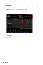
Page 58: ...to display the fan duty curve line yellow in fan operating windows 2 Click and drag the duty points to adjust the fan speed Duty points Select a fan to be adjusted Important The pictures in this section are for reference only and may vary from the motherboard you purchased ...

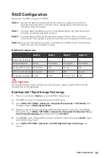
Page 59: ...ellent Excellent Excellent Read performance Excellent OK Good OK Write performance Excellent Good OK Good Capacity utilization 100 50 67 1 1 n 50 Important All the information volumes pictures listed in your system might differ from the illustrations in this appendix Enabling Intel Rapid Storage Technology 1 Power on and press Delete key to enter BIOS Setup menu 2 Press F7 to switch to Advanced mo...

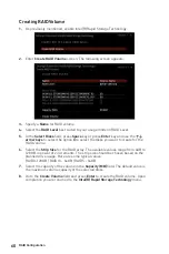
Page 60: ...u want to create for the RAID volume 6 Select the Strip Size for the RAID array The available values range from 4KB to 128 KB in power of 2 increments The strip size should be chosen based on the planned drive usage Here are some typical values RAID0 128KB RAID10 64KB RAID5 64KB 7 Select the capacity of the volume in the Capacity MB field The default value is the maximum volume capacity of the sel...

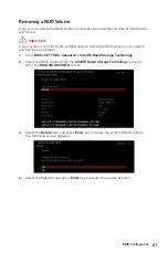
Page 61: ... system will become unbootable 1 Go to BIOS SETTING Advanced Intel R Rapid Storage Technology 2 Select the RAID volume from the Intel R Rapid Storage Technology screen to enter the RAID VOLUME INFO screen 3 Select the Delete item and press Enter key to delete the selected RAID volume The following screen appears 4 Select the Yes item and press Enter key to accept the volume deletion 61 RAID Config...

Page 62: ...t to non RAID item and press Enter to delete the RAID volume and remove any RAID structures from the drives The following screen appears 5 Select the Yes item and press Enter key to accept the disk reseting Important You will lose all data on the RAID drives and any internal RAID structures when you perform this operation Possible reasons to Reset Disks to Non RAID could include issues such as inc...

Page 63: ...nd restore data redundancy refer to the procedure below that corresponds to the current situation 1 Power off 2 Replace the failed hard drive with a new one that is of equal or greater capacity 3 Reboot the system and go to BIOS SETTING Advanced Intel R Rapid Storage Technology 4 Select the Degraded RAID volume from the Intel R Rapid Storage Technology screen to enter the RAID VOLUME INFO screen 5...

Page 64: ...disk USB drive in the computer until the system reboots itself Windows setup will need to copy the files after the RAID volume is formatted and Windows setup starts copying files Installing Intel Rapid Storage Technology Software 1 As previously mentioned enable Intel R Rapid Storage Technology in BIOS 2 Insert the MSI USB Drive into the optical drive 3 Click the Select to choose what happens with...

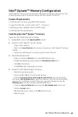
Page 65: ...Intel Optane memory module into the M 2 slot 3 Enable M 2 Optane Genie Power on and press Delete key to enter BIOS Setup menu Enable M 2 Optane Genie by clicking the M 2 Optane Genie item Click Ok in the dialog Press F10 to save configuration and exit 4 Install the Intel Rapid Storage Technology Reboot to operating system Insert the MSI USB Drive into the optical drive Click the Select to choose w...

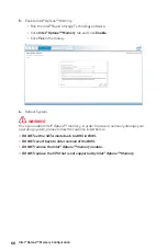
Page 66: ...ce you enable Intel Optane memory in order to prevent seriously damage your operating system please follow the cautions listed below DO NOT set the SATA mode back to AHCI in BIOS DO NOT revert back to older version of the BIOS DO NOT remove the Intel Optane memory module DO NOT replace the CPU that is not supported by Intel Optane Memory 66 Intel Optane Memory Configuration ...

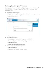
Page 67: ...ptane Memory Disable Intel Optane Memory via the Intel Optane memory application Intel Rapid Storage Technology Click Yes in the dialog Reboot System 2 Disable M 2 Optane Genie Press Delete key to enter BIOS Setup menu during POST Disable M 2 Optane Genie by clicking M 2 Optane Genie item Click Ok in the dialog Press F10 to save configuration and exit 3 Remove the Intel Optane memory module Power ...

Page 68: ...t the computer If 1 long 2 short beeps are heard remove and reinstall the graphics card and then restart the computer Test with another known working graphics card The computer does not boot after updating the BIOS Clear the CMOS Use the secondary BIOS to bootup the system Only for motherboard with Dual BIOS Lost BIOS password Clear the CMOS but that will cause you to lose all customized settings ...

Page 69: ...ers is MSI MSI NL Eindhoven 5706 5692 ER Son B급 기기 가정용 방송통신기자재 이 기기는 가정용 B급 전자파적합기기로서 주 로 가정에서 사용하는 것을 목적으로 하며 모 든 지역에서 사용할 수 있습니다 クラスB情報技術装置 この装置は クラスB情報技術装置です この 装置は 家庭環境で使用することを目的として いますが この装置がラジオやテレビジョン受 信機に近接して使用されると 受信障害を引き起こすこと があります 取扱説明書に従って 正しい取り扱いをして下さい VCCI B C Tick Compliance Battery Information European Union Batteries battery packs and accumulators should not be disposed of as unsor...

Page 70: ... de equipos electrónicos están obligados a hacerse cargo de dichos productos al termino de su período de vida MSI estará comprometido con los términos de recogida de sus productos vendidos en la Unión Europea al final de su periodo de vida Usted debe depositar estos productos en el punto limpio establecido por el ayuntamiento de su localidad o entregar a una empresa autorizada para la recogida de ...

Page 71: ... dei Materiali Elettrici ed Elettronici Direttiva 2002 96 EC in vigore dal 13 Agosto 2005 prodotti appartenenti alla categoria dei Materiali Elettrici ed Elettronici non possono più essere eliminati come rifiuti municipali i produttori di detti materiali saranno obbligati a ritirare ogni prodotto alla fine del suo ciclo di vita MSI si adeguerà a tale Direttiva ritirando tutti i prodotti marchiati ...

Page 72: ... l Co Ltd Copyright 2020 All rights reserved The MSI logo used is a registered trademark of Micro Star Int l Co Ltd All other marks and names mentioned may be trademarks of their respective owners No warranty as to accuracy or completeness is expressed or implied MSI reserves the right to make changes to this document without prior notice Revision History Version 2 0 2020 05 First release Technica...

Reviews: