background image

Overview

1-6

5

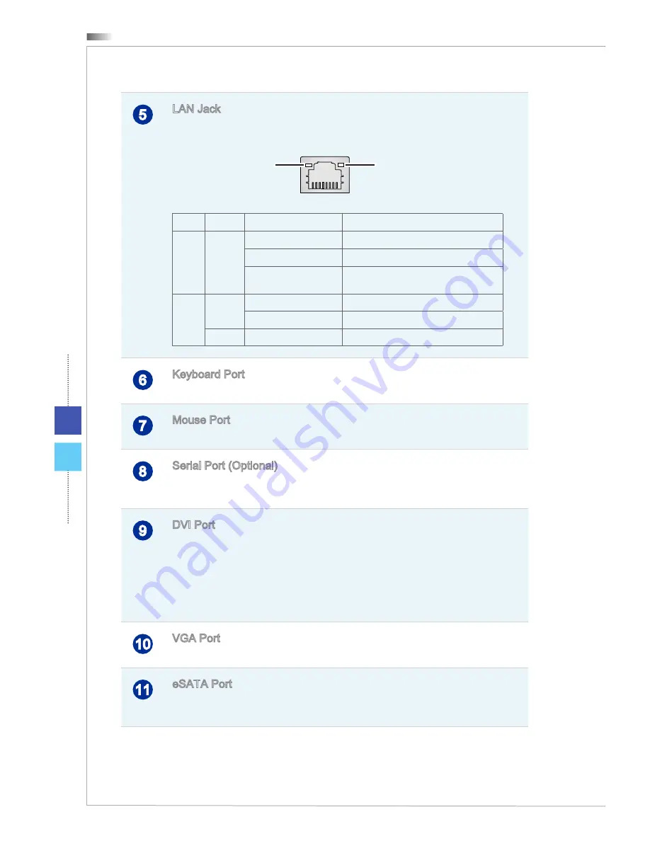
LAN Jack

The standard RJ-45 LAN jack is provided for connection to the Local 

Area Network (LAN). You can connect a network cable to it.

Green/ Orange

Yellow

LED

Color

LED State

Condition

Left

Yellow

Off

LAN link is not established.

On (steady state)

LAN link is established.

On (brighter & pulsing)

The  computer  is  communicating  with 

another computer on the LAN.

Right

Green

Off

10 Mbit/sec data rate is selected.

On

100 Mbit/sec data rate is selected.

Orange

On

1000 Mbit/sec data rate is selected.

6

Keyboard Port

The standard PS/2 keyboard DIN connector is for a PS/2 keyboard.

7

Mouse Port

The standard PS/2 mouse DIN connector is for a PS/2 mouse.

8

Serial Port (Optional)

The serial port supports barcode scanners, barcode printers, bill 

printers, credit card machine, etc.

9

DVI Port

The DVI (Digital Visual Interface) connector allows you to connect a 

LCD monitor. It provides a high-speed digital interconnection between 

the computer and its display device. To connect an LCD monitor, sim-

ply plug your monitor cable into the DVI connector, and make sure that 

the other end of the cable is properly connected to your monitor (refer 

to your monitor manual for more information.)

10

VGA Port

The DB15-pin female port is provided for monitor.

11

eSATA Port

The  eSATA  (External  Serial  ATA)  port  is  provided  for  attaching  the 

eSATA external hard drive.

12

HDMI Port

The High-Definition Multimedia Interface (HDMI) is an all-digital audio/ 

video interface capable of transmitting uncompressed streams. HDMI 

supports all TV format, including standard, enhanced or high-definition 

video, plus multi-channel digital audio on a single cable.

13

Audio Jack

Line-In (Blue) is used for external CD player, tapeplayer or other audio 

devices.

Line-Out (Green) is used for speakers or headphones.

Mic (Pink) is used for microphones.

Summary of Contents for Hetis H61 Ultra

Page 1: ...G52 B0501X1 Hetis H61 Ultra Personal Computer MS B050 System ...

Page 2: ...Frequency Interference Statement viii WEEE Statement ix 1 Overview 1 1 Packing Contents 1 2 System Overview 1 3 System Specifications 1 8 Component Replacement Upgrade 1 10 2 Getting Started 2 1 Safety Comfort Tips 2 2 Connecting Peripheral Devices 2 3 Hardware Setup 2 8 3 System Operations 3 1 System Booting Setup for the first time 3 2 Creating System Recovery Disc 3 3 Network Connection under W...

Page 3: ...ement and we reserve the right to make changes without notice Trademarks All trademarks are the properties of their respective owners MSI is a registered trademark of Micro Star Int l Co Ltd Intel is a registered trademark of Intel Corporation Windows is a registered trademark of Microsoft Corporation Realtek is a registered trademark of Realtek Semiconductor Corporation PS 2 is registered tradema...

Page 4: ...se be noticed that the acquisition of replaceable parts or compatible ones of the product users purchased in certain countries or territories may be fulfilled by the manufacturer within 5 years at most since the product has been discontinued depending on the official regulations declared at the time Please contact the manufacturer via http support msi com for the detailed infor mation about the ac...

Page 5: ...n through take back policy Environmental Policy The product has been designed to enable proper reuse of parts and recycling and should not be thrown away at its end of life Users should contact the local authorized point of collection for recycling and disposing of their end of life products Visit the MSI website and locate a nearby distributor for further recycling information Users may also reac...

Page 6: ...outlet Do not disable the protective earth pin from the plug The equipment must be connected to an earthed mains socket outlet Always unplug the AC power cord before installing any add on card or module to the equipment Always disconnect the AC power cord or switch the wall socket off if the equipment would be left unused for a certain time to achieve zero energy consumption The ventilator on the ...

Page 7: ... shield is reliably connected to protective earthing sys tem of the building Cable distribution system should be grounded earthed in accordance with ANSI NFPA 70 the National Electrical Code NEC in particular Sec tion 820 93 Grounding of Outer Conductive Shield of a Coaxial Cable Always keep the strong magnetic or electrical objects away from the equipment If any of the following situations arises...

Page 8: ...elevision reception which can be determined by turning the equipment off and on the user is encouraged to try to correct the interference by one or more of the measures listed below Reorient or relocate the receiving antenna Increase the separation between the equipment and receiver Connect the equipment into an outlet on a circuit different from that to which the receiver is connected Consult the...

Page 9: ...icados como eléctricos y equipos electrónicos no pueden ser depos itados en los contenedores habituales de su municipio los fabricantes de equipos elec trónicos están obligados a hacerse cargo de dichos productos al termino de su período de vida Italian Italiano In base alla Direttiva dell Unione Europea EU sullo Smaltimento dei Materiali Elettrici ed Elettronici Direttiva 2002 96 EC in vigore dal...

Page 10: ...02 96 EC platné od 13 srpna 2005 je zakázáno likvidovat elek trické a elektronické výrobky v běžném komunálním odpadu a výrobci elektronických výrobků na které se tato směrnice vztahuje budou povinni odebírat takové výrobky zpět po skončení jejich životnosti Traditional Chinese 繁體中文 歐盟已制訂有關廢電機電子設備法令 亦即自2005年8月 13日生效的2002 96 EC 明文規定 電機電子設備產品 不可再以都市廢棄物處理 且所 有相關電子設備製造商 均須在產品使用壽命結束後進行回收 Simplified Chi...

Page 11: ... e Electrónicos da União Europeia UE efectiva desde o 13 de Agosto do ano 2005 os produtos de equipamento eléctrico e electrónico não podem ser descartados como resíduo municipal e os fabricantes do equipamento electrónico sujeitos a esta legislação estarão obligados a recolhar estes produtos ao finalizar sua vida útil Swedish Svenska Under Europeiska unionens EU Weee direktiv Waste Electrical and...

Page 12: ...ия съюз относно отпадъците от електрическо и електронно оборудване директива 2002 96 EC важаща от 13 август 2005 г електрическо и електронно оборудване не може да се изхвърля заедно с битовите отпадъци и производителите на такова оборудване са задължени да приемат обратно съответните продукти в края на експлоатационния им период Croatian Hrvatski U okviru Direktive Europske Unije EU o Otpadnim ele...

Page 13: ...urchasing the Hetis H61 Ultra MS B050 System This system is your best slim PC choice With the fantastic appearance and ultrasmall form factor it can easily be set anywhere The feature packed plat form also gives you an exciting PC experience ...

Page 14: ... Stand AC Power Cord Driver Utility Disk User Manual Please contact us immediately if any of the items is damaged or missing The illustrations are for reference only and your packing contents may slightly vary depending on the model you purchased ...

Page 15: ...r other USB compatible devices It supports up to 5Gbit s SuperSpeed data transfer rate The USB 3 0 port is back ward compatible with USB 2 0 devices 4 Power Button LED Press the power button to turn the system on and off The power LED glows when the system is turned on and goes off when the system is shut down In terms of power saving the LED blinks in S3 Suspend to RAM mode and goes off in S4 Sus...

Page 16: ... is detected 6 Optical Disk Drive A DVD Super Multi drive is integrated for your home entertainment Blu ray is optional 7 Eject Button Press the eject button to open and close the optical disk drive Important High speed devices are recommended for USB 3 0 ports whereas low speed devices such as mouse or keyboard are suggested to be plugged into the USB 2 0 ports on the rear panel ...

Page 17: ...on is the circle Make sure the power supply switch to the on position before you press the pow er button to turn on your system 3 Ventilator The ventilator on the enclosure is used for air convection and to pre vent the equipment from overheating Do not cover the ventilator 4 USB 2 0 Port The USB Universal Serial Bus port is for attaching USB devices such as keyboard mouse or other USB compatible ...

Page 18: ...S 2 keyboard 7 Mouse Port The standard PS 2 mouse DIN connector is for a PS 2 mouse 8 Serial Port Optional The serial port supports barcode scanners barcode printers bill printers credit card machine etc 9 DVI Port The DVI Digital Visual Interface connector allows you to connect a LCD monitor It provides a high speed digital interconnection between the computer and its display device To connect an...

Page 19: ...smitting uncompressed streams HDMI supports all TV format including standard enhanced or high definition video plus multi channel digital audio on a single cable 13 Audio Jack Line In Blue is used for external CD player tapeplayer or other audio devices Line Out Green is used for speakers or headphones Mic Pink is used for microphones ...

Page 20: ...Supports PCI Express LAN Gigabit Ethernet by Realtek RTL8111E or Intel WG82579V Optional Supports ACPI Power Management Compliant with PCI 2 3 Audio HDA Codec by Realtek ALC887 Flexible 6 channel audio with jack sensing Compliant with Azalia 1 0 spec Input Output I O 5 audio jacks 4 USB 2 0 ports 2 USB 3 0 ports 1 power jack 1 power switch 1 LAN jack 1 mouse port 1 keyboard port 2 serial ports Opt...

Page 21: ...tra Storage 3 5 Hard Disk Drive 5 25 Optical Disk Drive Power Supply 270 watt PSU with active PFC Voltage Value Auto Switch Dimension 385 mm D x 340 mm W x 94 mm H with stand 385 mm D x 330 mm W x 94 mm H without stand ...

Page 22: ...mitation please refer to the specifications in the User s Manual For any further information on the product users purchased please contact the local dealer Do not attempt to upgrade or replace any component of the product if you are not an authorized dealer or service center since it may cause the warranty void It is strongly recommended that you contact the authorized dealer or service center for...

Page 23: ...ng Started This chapter provides you with the information on hard ware setup procedures While connecting peripheral devices be careful in holding the devices and use a grounded wrist strap to avoid static electricity ...

Page 24: ...posture when operating When sitting on the chair sit straight and keep a good posture Adjust the chair s back if available to support your back comfortably Place you feet flat and naturally on the floor so that your knees and elbows have the proper position about 90 degree when operating Put your hands on the desk naturally to support your wrists Avoid using your PC in a place where discomfort may...

Page 25: ... devices listed here are for reference only Connecting Serial Devices Serial ports are commonly used in applications such as industrial automation systems scientific analysis shop till systems and some industrial consumer products Users may connect barcode scanners barcode printers bill printers and credit card machine to this serial port ...

Page 26: ... associated cabling are always used solely to carry analog video signals along with digital clock and data HDMI High Definition Multimedia Interface is a new interface standard for PCs dis plays and consumer electronics devices that supports standard enhanced and high definition video plus multi channel digital audio on a single cable To connect the VGA HDMI device first make sure the Hetis H61 Ul...

Page 27: ...ical storage device and etc To connect these devices install the drivers for each device first if necessary and then connect the device to the Hetis H61 Ultra This Hetis H61 Ultra is capable of auto detecting the USB devices installed and if there is no detection of the devices please manually enable the USB devices by going to Start Menu Control Panel Add Hardware to add the new device ...

Page 28: ...ctor of the Hetis H61 Ultra allows you to connect the LAN local area network devices such as a hub switch and gateway to build a network connection For more instructions or detailed steps on connecting to the LAN please ask your MIS staff or network manager for help ...

Page 29: ...ternal Serial ATA hard disk device The eSATA standard interface supports plug and play technology so that you can connect and remove the eSATA devices without turning off the Hetis H61 Ultra To connect the eSATA hard disk device simply connect the cable of the device to the eSATA Connector of your Hetis H61 Ultra ...

Page 30: ... the male end to the electrical outlet Disconnecting the AC Power 3 Unplug the AC power cord from the electrical outlet first 4 Unplug the AC power cord from the Hetis H61 Ultra 2 3 4 1 Important When unplugging the AC power cord always hold the connector part of the cord Never pull the cord directly Powering on the System Press the power button to power on the system ...

Page 31: ...ns such as system boot setup recovery disc creation network connection and so on Important It is highly recommended that you create a system re covery disc as the backup solution in the event of a catastrophic disk failure or other accidents All information is subject to change without prior no tice ...

Page 32: ...ox and click Next to continue 7 Select Use recommended settings for Help protect your computer and improve Windows automatically 8 Review your time and date settings Click Next to continue 9 Please choose a wireless network you intend to join from the provided WLAN list Click Next to continue You may also click Skip to skip this step and set up the WLAN later 10 Optional Followingly comes the anti...

Page 33: ...ailure or other accidents Before moving forward please make sure your system booting setup is complete and go over the following procedures to get it done 1 Double click the BurnRecovery icon on the desktop to launch the Recovery Disc Creation Tool Please note that it may take a while for the operating system to prepare recovery files 2 Click Next to start the image creation of the recovery disc ...

Page 34: ...4 3 Select Create and burn a recovery disc and click Next to continue Alternatively choose Advanced to bring forth advanced options 4 The image of recovery disc is being created It takes some time to finish the pro cessing ...

Page 35: ...ions to prepare enough number of blank DVD discs Insert the blank DVD disc into the optical disc drive and click Next to continue 6 The Windows Disc Image Burner pops up Click Burn to start the burning progress It takes a while to finish the processing ...

Page 36: ... of the disc creation click Close to exit and take out the disc Follow the on screen instructions to create all recovery discs 8 All recovery discs have been successfully created Please store the discs carefully and click Next to continue ...

Page 37: ...3 7 Hetis H61 Ultra 9 Check the following box if you want to remove the temporary files Click Finish to complete recovery disc creation ...

Page 38: ...System Operations 3 8 Network Connection under Windows Wired LAN 1 Go to Start Control Panel 2 Select Connect to the Internet under Network and Internet ...

Page 39: ... Ultra 3 Select Broadband PPPoE to connect using DSL or cable that requires a user name and password 4 Type the information from your Internet Service Provider ISP and click Connect to establish your LAN connection ...

Page 40: ...ff your display or set your PC to sleep mode after a period of user inactivity Power Management in Windows OS Power Options in Windows OS allow you to control the power management features of your display hard drive and battery Go to Start Control Panel System and Security Then click on the Power Options link Select a power plan that suits your personal needs You may also fine tune the settings by...

Page 41: ...set to behave in the following ways when the system is operating on AC power Turn off the display after 15 minutes Initiate Sleep after 30 minutes Waking the System Up The computer shall be able to wake up from power saving mode in response to a com mand from any of the following the power button the network Wake On LAN the mouse the keyboard Energy Saving Tips Turn off the monitor by pressing the...

Page 42: ...o install the OS with other built in languages Before using the System Recovery Function please backup the important data saved on your system drive to other storage devices If the following solution fails to recover your system please contact the authorized local distributor or service center for further assistance Recovering the System with the F3 Hotkey If the system encounters non recoverable ...

Page 43: ...on will get your system back to default settings Press OK to confirm 5 Press OK to reconfirm and start the System Recovery Function Alternatively press Cancel to stop 6 The System Recovery Function is proceeding now 7 The following message indicates successful system recovery Press OK to restart the system and access the Windows operating system as usual ...

Page 44: ...llow the instructions below to continue 1 Insert the recovery disc into the optical disc drive and restart the system 2 Press the F11 hotkey on the keyboard when the following image appears 3 Select the CD DVD device as the boot device and press Enter to confirm the selection Press any key to reconfirm the selection when the following message appears 4 The Windows OS starts loading files ...

Page 45: ...except a clear cleanup of the HDD System Partition Recovery will format the C drive only Only the C drive will be restored to manufacturer default Other drives will not be affected It is highly recom mended that users select System Partition Recovery to restore the system 6 The system recovery will format your HDD partition Make sure that the important data have been backed up Click YES to continu...

Page 46: ...ction or it may cause unknown damage to the system 8 The following message indicates successful system recovery Press OK to restart the system and access the Windows operating system as usual 9 If the recovery process is interrupted or failed please repeat the recovery procedures from the beginning ...

Reviews: