MSE CENTAUR 2 Instruction Manual Download Page 18

 
ROTORS AND ACCESSORIES 

18 


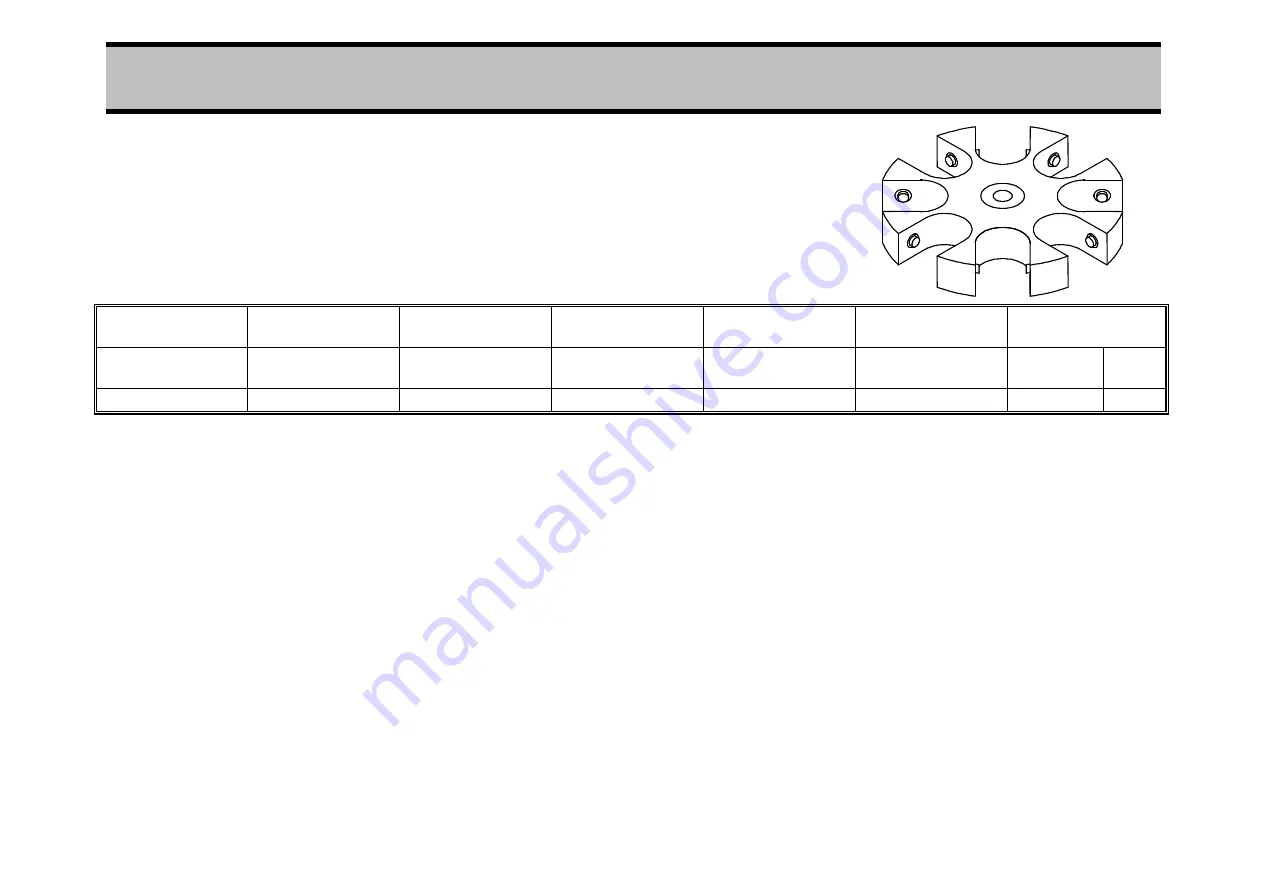
4.5.3  8 Place Swing out rotor 

43121-111 
(includes buckets and spindle nut)


Bucket 

Trunnion 

Adaptor/ 

Cushion 

Rotor 

Capacity 

Max.* 

Speed 

Max. 

RCF 

Max. Tube Size 


Dia 

(mm) 

Ht 

(mm) 

34411-905# 


34142-101** 

8 x 15ml 

3500 

2200 

17 

115 


Summary of Contents for CENTAUR 2

Page 1: ...Instruction Manual For CENTAUR 2 CENTRIFUGE READ BEFORE USE Models MSB020 CX1 5 MSB020 CX1 1 71100 493 4 ...

Page 2: ...n in the manual normal common sense safety precautions must be taken at all times to avoid the possibility of accidents Particular care is required when working with apparatus at high temperature or pressure 4 Installation maintenance repairs and servicing should only be carried out by a MSE UK Ltd approved engineer and suitably trained personnel should only carry out connection to electrical supp...

Page 3: ...s lid seals O rings or lamps are excluded MSE UK Ltd or its approved service agent reserves the right to repair defective equipment on the premises of the customer or at a service station at the sole discretion of MSE UK Ltd or their approved agent In the event of return to an approved service centre the customer is responsible for the safe packaging of the instrument and notification to the servi...

Page 4: ...e following code 220v 240v 110v 120v Live Brown Black Neutral Blue White Earth Green and Yellow Green Connect the wires to a non reversible 3 pin plug as follows Green and Yellow or Green to terminal marked E Earth G Ground coloured Green or Green and Yellow or marked with the Earth symbol Blue or White wires to terminal marked N Neutral or Common or coloured Blue Brown or Black wires to terminal ...

Page 5: ...out rotor 16 4 5 2 4 Place Swing out rotor 17 4 5 3 8 Place Swing out rotor 18 4 5 4 8 Place Angle rotor 19 4 5 5 12 Place Angle rotor 20 5 OPERATION 21 5 1 Run Procedure 21 5 2 Stop Procedure 21 5 3 Imbalance 21 5 4 Motor Thermal Cut out 21 5 5 Power Failure 21 5 6 Lid Safety Circuit 22 6 MAINTENANCE 23 6 1 Cleanliness 23 6 2 Drive Shaft 23 6 3 Prevention Of Corrosion 23 6 4 O Rings 23 6 5 Steril...

Page 6: ...d Indication 30 8 5 Lid Safety Circuit 30 8 6 Balance Circuit 30 9 ESSENTIAL PARTS LIST 32 9 1 Body Assembly 32 9 2 Lid and Associated Assembly 32 9 3 Motor Assembly 33 9 4 PCB A Assembly 33 9 5 PCB D Assembly 33 9 6 Instrument Chassis Assembly 34 10 PRODUCT DISPOSAL ISO 14001 COMPLIANCE 34 11 HOW TO OBTAIN SERVICE ON YOUR FALCON CENTRIFUGE 35 ...

Page 7: ... The following materials are prohibited Flammable or explosive materials Materials which chemically interact vigorously The load must be distributed symmetrically round the rotating assembly so that it is evenly balanced and complies with the manufacturer s instructions in this respect After use the sleeves and adaptors in centrifuge rotors should be removed to allow thorough cleaning of rotors an...

Page 8: ...r EC Directive standard used 120v units designed for CSA approval to the following standards CAN CSA C22 2 No 1010 1 92 CAN CSA C22 2 No 1010 2 020 94 INDEPENDENT SPEED SENSING 120 volt Machines only To comply with certain USA standards the 120 volt machines are fitted with a small window in the cover This permits independent speed check directly from the rotor with use of an optically coupled tac...

Page 9: ...the centrifuge for continuous running until manually reset to Off 4 The Rev min indicator is a digital display giving continuous read out of the rotational speed of the rotor rounded off to the nearest hundred rev min e g 2500 3200 5 The Speed control allows selection of any speed between 300 rev min and the maximum allowed for the rotor in use see section 4 5 Rotors And Accessories Tables as indi...

Page 10: ...the front move the point towards the rear against a slight spring pressure to actuate the lid lock mechanism Press the lid actuator to the right and open the lid The lid is friction controlled to remain open at any intermediate position desired Front Figure 2 Manual Over ride of Lid Lock 2 4 Specifications Dimensions Height 336mm with lid open 470mm Width 436mm Depth 487mm Weight 36kg without roto...

Page 11: ...scription Quantity 32600 019 Fuse 5A 20mm 1 76600 004 Lid Lock Release Key 1 88110 024 Lid Seal Insertion Tool 1 71100 493 Operating Manual 1 71100 958 Guarantee Card 240V 1 71100 1052 Guarantee Card 120V 1 82120 143 Spindle Nut 1 for Rotors 34121 607 34117 603 34117 604 only ...

Page 12: ... position NOTE Laboratory management procedures should require that no person or any hazardous materials are within a 300mm boundary while the centrifuge is operating 3 2 Connecting To 3 Pin Plug Connect the 3 core cable to a 3 pin plug fitted with a 5 Amp fuse as follows WARNING This equipment must be earthed Brown wire to Live L Terminal Blue wire to Neutral N Terminal Yellow Green wire to Earth...

Page 13: ...it to the bracket See Figure 3 Figure 3 Securing Centrifuge to work surface using Bench fixing Kit Part No 41159 188 If the restraint kit is not used to secure the centrifuge on the bench then it is the recommendation of BS EN61010 2 020 that a clearance of 300mm is allowed around the base of the centrifuge when in the final operating position NOTE Laboratory management procedures should require t...

Page 14: ...ctions 0 4 5 engage and tighten the spindle nut finger tight 4 2 Removal Of Rotor Press Power switch off Open the centrifuge lid Remove all rotor accessories i e buckets trunnions etc Loosen the spindle nut a few turns grip the rotor as illustrated in Figure 4 and pull upwards with the fingers whilst gently rocking the rotor and applying downward pressure with the thumbs to release it from the dri...

Page 15: ...f the rotor Finally if using a swing out rotor check that all cups of trunnion rings swing freely If necessary apply a light smear of petroleum jelly to the rotor pivot slots Failure to load the rotor correctly can result in serious imbalance and possible damage to the centrifuge Biologically hazardous material should only be centrifuged in sealed buckets or cups 4 4 Rotor Speed Maximum Speeds of ...

Page 16: ...26 includes spindle nut Cup Set of 4 Adaptor Set of 4 Rotor Capacity Max Speed Max RCF Max Tube Size Dia mm Ht mm Sealed Cup 43551 121 4 x 200ml 3300 2000 57 116 43551 121 34159 302 brown 4 x 100ml 3300 2000 39 5 113 43551 121 34159 301 yellow 4 x 50ml 3300 2000 29 113 43551 121 34159 304 green 28 x 15ml 3300 2000 17 110 43551 121 34159 303 grey 16 x 10ml DSS 3300 2000 16 5 105 43551 121 34159 305...

Page 17: ...130 30 118 34411 909 34148 705 4 x 50ml 4200 3130 conical 29 112 Sealing cap assy 34141 114 4 x 1oz 4200 3130 Glass 43561 606 can be 34141 115 4 x 1oz 4200 3130 Sterilin used if required 34144 307 4 x 15ml 4200 3130 17 5 110 34153 304 24 x Haem 4200 3130 7 7 120 34151 301 8 x Wass 4200 3130 12 7 120 34411 904 34136 102 34142 101 8 x 15ml 4000 2612 17 120 34136 103 34142 101 16 x 15ml 3400 2000 17 ...

Page 18: ...ORIES 18 4 5 3 8 Place Swing out rotor 43121 111 includes buckets and spindle nut Bucket Trunnion Adaptor Cushion Rotor Capacity Max Speed Max RCF Max Tube Size Dia mm Ht mm 34411 905 34142 101 8 x 15ml 3500 2200 17 115 ...

Page 19: ... mm Ht mm 34411 909 34142 104 8 x 50ml 4600 3120 29 110 34411 909 34148 705 8 x 50ml 4600 3120 conical 29 110 34411 909 34141 114 8 x 1oz 4600 3120 Glass 34411 909 34141 115 8 x 1oz 4600 3120 Sterilin 34411 909 34144 307 8 x 15ml 4600 3120 17 5 110 34411 909 34153 304 48 x Haem 4600 3120 7 7 120 34411 909 34151 301 16 x Wass 4600 3120 12 7 120 ...

Page 20: ...F Max Tube Size Dia mm Ht mm 34411 904 34142 101 12 x 15ml 4600 3000 17 110 34411 904 43161 103 12 x 15ml 4600 3000 conical 17 110 34411 904 34148 101 12 x Haem 4600 3000 7 7 110 34411 904 34146 104 12 x 5 or 3ml 4600 3000 13 120 34411 904 34146 103 12 x 2ml 4600 3000 12 100 34411 904 34146 102 12 x 0 5 or 1ml 4600 3000 9 100 ...

Page 21: ...mer to off and wait thirty seconds then turn the Power switch on The lid unlocked indicator will come on open the lid check the balance of the rotor close the lid and restart the run 5 4 Motor Thermal Cut out The motor is fitted with a self re setting thermal cut out to protect the motor from over heating If the thermal cut out has operated during a run the rotor will stop and 0000 will be display...

Page 22: ...rt of the lid safety circuit These can be checked for correct operation as follows i Press Power switch on and open the lid The Lid Unlocked indicator lamp should be off ii Close the lid The Lid Unlocked indicator lamp should come on If the lamp does not come on check that the lid is firmly closed as this is the most likely cause of malfunction iii Switch the Timer to Hold or select a Time The Lid...

Page 23: ... store inverted in a dry place Rotors should be protected with MSE Rotor Spray Cat No 17341 151 which is an anti corrosion and de waterising agent In addition rotors should be periodically inspected by a responsible person so that corrosion can be detected at the onset Contact MSE UK Ltd Technical Support for further advice on this subject 6 4 O Rings Ensure O Rings are lightly coated with silicon...

Page 24: ...cated in the slot and the brush pushed fully into the carrier against the tension of the roll spring Hold the assembly together with the roll spring in the same relationship to brush and motor as when the old brush was removed and insert the front end into the brush housing of the motor Take care to ensure that the tongue of the roll spring lies facing forward flat with the carrier if not gently p...

Page 25: ...he bowl Lower the bowl applying slight downward pressure with a twisting motion and ease downwards until the seal lip is just under the bowl rim with the vent in the bowl in original noted position Insert the lid seal tool Figure 5 between the seal and the lip of the bowl and ease the seal over the lip of the bowl while applying downward pressure on the bowl centre boss Work the tool round the rim...

Page 26: ... centrifuge and frequency meter displays 7 2 Removal Of The Motor Ensure that there is no rotor on the drive shaft With the centrifuge turned on to its back and the instrument chassis removed section 6 7 remove the remaining screws around the edges of the base plate Making a note of terminations and connections for reference disconnect plugs and wires and remove the base plate with motor The upper...

Page 27: ...in its operating position insert a 1mm thick gauge between the microswitch actuator and the side of the tacho box Item 6 Figure 6 By turning the Balance detector adjusting screw Item 7 Figure 6 adjust the microswitch towards the side of the tacho box until the microswitch just operates breaks Ensure that the microswitch operates re makes when the gauge is removed ...

Page 28: ...SERVICING 28 Figure 6 Partially Exploded View Of Centaur 2 ...

Page 29: ... the pulse is used to chop a sine wave in order to vary the speed The feedback network R18 MR10 discharges the capacitor to give a narrow trigger pulse thus reducing the power requirement on the 12 Volt supply to IC1 Voltage is fed to the speed control network via the Lid Closed and the Lid Locked micro switches SW2 and SW3 and one contact of the Timer switch SW4 1 so that the motor is driven only...

Page 30: ... soon as the rotor stops the circuit comprising IC4 pins 1 2 3 4 5 and 6 IC3 pins 1 2 and 3 together with VT2 monitors that the run down is normal and if so discharges the capacitor C8 The method employed uses the outputs of two frequency discriminators IC4 pins 5 and 6 directly and IC4 pins 1 2 3 and 4 after a delay as inputs to a NOR gate If the 60 rev min discriminator operates sufficiently in ...

Page 31: ...CIRCUIT DESCRIPTION 31 ...

Page 32: ... Button 72100 121 Left hand Side Panel 72100 120 Right hand Side Panel 88120 040 Lid Stop 8 8 Lid and Associated Assembly 72900 045 Left hand Torsion Spring 72900 046 Right hand Torsion Spring 72100 122 Lid Handle 88120 039 Catch Pin 72900 048 Catch Spring 36020 028 Micro Switch Lid Closed SW2 36020 027 Micro Switch Lid Lock SW3 60800 001 Solenoid Lid Lock 72900 047 Solenoid Spring Lid Lock 72900 ...

Page 33: ...ssembly 43040 042 Opto isolator 4N33 IC1 43040 029 Transistor Driver ULN2004 IC2 43030 003 Quad NOR Gate 4001 IC3 43030 002 Schmitt Trigger 74C14 or 40106 IC4 46060 039 Transistor BC184L 30V 200mA NPN VT1 VT2 46080 013 Triac MR1 42040 012 Diode IN4002 MR2 42030 020 Diode Bridge KBPC 104 400V 2A MR3 42040 013 Diode IN4148 MR4 5 7 8 9 10 11 12 13 14 15 16 17 42020 024 Zener Diode BZX61 8 2V 1 3W MR6...

Page 34: ...or Lamp Amber Lid Unlocked 35080 046 Relay RLA 46100 003 Filter 38900 042 Transformer TR1 9 Product Disposal ISO 14001 Compliance This product should be treated as industrial waste and disposed of accordingly There are no toxic material used in the manufacture of this product The majority of materials used in this product are recyclable and all can be disposed of safely Where the product has refri...

Page 35: ...97 Fax 44 0 208 650 8408 E mail sales mseuk co uk 1 Contact the repairs centre have the model serial number and date of purchase and fault description available 2 You will be given a return goods authorisation number and directions for shipping 3 Remove all rotors buckets and adapters Do not ship these items only the centrifuge 4 Thoroughly clean and disinfect the centrifuge 5 Fill out the attache...

Page 36: ...ensure you receive the best and fastest service possible Model Serial number on plate at back of unit Date purchased Where purchased Brief description of fault Date fault first occurred Date repair centre contacted Authorisation number Condition of centrifuge Has it been disinfected Yes No Disinfectant used Contact name Address Telephone Number Signature ...

Reviews: