MSA ZGARD CX II Instruction Manual Download Page 19


Section 9 

ZGARD CX II Controller 
Operation & Configuration Set Up Menu


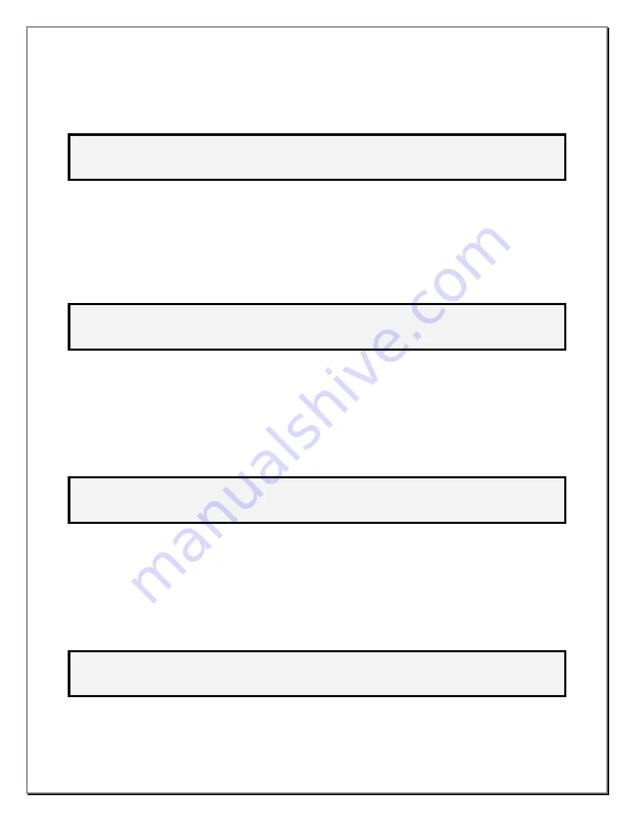
7.2. The  screen  example  below  will  appear  and  report  that  sensor  24  has  been  changed. The  user  will  be 

asked to verify the Warning and Alarm set points. Press the menu key to accept and continue. 

A  U  T  O  -  C  O  N  F  I  G  :    S  C  A  N  N  I  N  G  .  .  .   


2  4 


>  >  >    V  E  R  I  F  Y     W  A  R  N  I  N  G     &    A  L  A  R  M    S  E  T  P  O  I  N  T  S 


<  <  < 


  M  E  N  U  :  C  O  N  T  I  N  U  E 


8.  Press the MENU key. 

9.  The 

CAUTION SETPOINT 

menu will appear. The second line of the display shows the current sensor # to 

be  assigned  a  caution  set-point  level.  The  sensor  range  is  also  shown  for  reference  only.  The  third  line 
shows the gas type and current set point. The following choices are available: 

9.1. 

Change  set  point:


Type  the  new  caution  set  point  (cannot  exceed  the  RANGE  value  shown)  and 

press ENTER. 

9.2. 

Go to next sensor #:

 Press the 

 or 

 key to move through all of the sensor numbers. 

C  A  U  T  I  O  N    S  E  T  P  O  I  N  T 


  S  E  N  S  O  R    #  :   


  R  A  N  G  E  :   

  1  0  0    P  P  M   


  S  E  T  P  O  I  N  T  :   


  2  5    P  P  M   


  G  A  S  :    C  O   


<  ,  > 

:  S  E  N  S  O  R   


0  .  .  9 

:  V  A  L  U  E   


  E  N  T  E  R  :  A  C  C  E  P  T 


10.  Press the MENU key. 

11.  The 

WARNING SETPOINT 

menu will appear. The second line of the display shows the current sensor # to 

be  assigned  a  warning  set-point  level.  The  sensor  range  is  also  shown  for  reference  only.  The  third  line 
shows the gas type and current set point. The following choices are available: 

11.1. 

Change  set  point:


Type  the  new  warning  set  point  (cannot  exceed  the  RANGE  value  shown)  and 

press ENTER. 

11.2. 

Go to next sensor #:

 Press the 

 or 

 key to move through all of the sensor numbers. 

W  A  R  N  I  N  G    S  E  T  P  O  I  N  T 


  S  E  N  S  O  R    #  :   


  R  A  N  G  E  :   

  1  0  0    P  P  M   


  S  E  T  P  O  I  N  T  :   


  2  5    P  P  M   


  G  A  S  :    C  O   


<  ,  > 

:  S  E  N  S  O  R   


0  .  .  9 

:  V  A  L  U  E   


  E  N  T  E  R  :  A  C  C  E  P  T 


12.  Press the MENU key. 

13.  The 

ALARM SETPOINT

 menu will appear. The second line of the display shows the current sensor # to be 

assigned an alarm set-point level. The sensor range is also shown for reference only. The third line shows 
the gas type and current set point. The following choices are available: 

13.1. 

Change set point:

 Type the new alarm set point (cannot exceed the RANGE value shown) and press 

ENTER. 

13.2. 

Go to next sensor #:

 Press the 

 or 

 key to move through all of the sensor numbers. 

A  L  A  R  M    S  E  T  P  O  I  N  T   


  S  E  N  S  O  R    #  :   


  R  A  N  G  E  :   

  1  0  0    P  P  M   


  S  E  T  P  O  I  N  T  :   


  5  0    P  P  M   


  G  A  S  :    C  O   


<  ,  > 

:  S  E  N  S  O  R   


0  .  .  9 

:  V  A  L  U  E   


  E  N  T  E  R  :  A  C  C  E  P  T 


8.2 


Summary of Contents for ZGARD CX II

Page 1: ...ment avec ses instructions Comme tout appareil complexifi ce produit peut vous donner les r sultats anticip s seulement s il est install usag et que le service d entretien sont effectu s d apr s les i...

Page 2: ...ufacturers of such components THIS WARRANTY IS IN LIEU OF ALL OTHER WARRANTIES EXPRESSED IMPLIED OR STATUTORY AND IS STRICTLY LIMITED TO THE TERMS HEREOF SELLER SPECIFICALLY DISCLAIMS ANY WARRANTY OF...

Page 3: ...llation and as a routine inspection of the system 5 Use only genuine MSA replacement parts when performing any maintenance procedures provided in this manual Failure to do so may seriously impair inst...

Page 4: ...ays 8 3 Section 9 Operation Configuration Set Up Menu Auto Configuration 9 0 Auto Configuration continued 9 1 Auto Configuration continued Caution Warning and Alarm setup 9 2 Zone Assignment External...

Page 5: ...the operating alarm and fault diagnostic status of the system The display is split in two display mode sections Status Display Common LED s for System OK Green Caution Amber Warning Amber and Alarm Re...

Page 6: ...etermine the capacity designation and number of remote gas sensors and configure the controller according to the required application Also refer to the ZGARD CX II controller Installation Outline draw...

Page 7: ...1 500 meters away from the controller The ZGARD CX II Controller does NOT provide operating power for the Remote Relay Modules REMOTE RELAY MODULE SPECIFICATIONS Operating Power 17 27VAC 50 60 Hz or...

Page 8: ...the remote sensors or group of sensors exceeds a predetermined caution threshold then the common Caution LED located above the LCD Screen will indicate a caution event Relay outputs can be pre assigne...

Page 9: ...ntroller can then execute control functions based on each zone By adding optional Remote Relay Modules RRM s distributed control can be achieved in addition to the internal control via the relays insi...

Page 10: ...y 1 42001 Relay 2 Etc 42039 Relay 40 The following data is available for each SENSOR 40xx0 Enable State Gas ID 0 Disabled 1 99 GasID 40xx1 Status 0 OK 1 Fail 2 Caution 4 Warning 8 Alarm 40xx2 Zone Ass...

Page 11: ...ect Zone 1 8 511 518 No Sensors Zone 1 8 Multi State 101 199 Alarm State Sensor 1 99 201 299 Zone Assignment Sensor 1 99 301 399 RS 485 Port Sensor 1 99 401 499 GasID Sensor 1 99 Binary 1 40 Relay Sta...

Page 12: ...es not scan the remote sensors and does not activate any warning or alarm relays An automatic timeout returns the ZGARD CX II to normal operation if no keypad activity is detected for 1 minute while i...

Page 13: ...each their respective warning level then the sensor numbers will be displayed adjacent to the W descriptor Should the number of sensors in a warning condition exceed the physical space provided then a...

Page 14: ...of remote sensors and is sequentially updated every 2 seconds Column1 The term ZONE reports the zone numbers Column2 The term SNS reports the number of sensors allocated to the current Zone Column3 Th...

Page 15: ...9 3 2 1 1 O K 1 9 6 0 P P M C O A L A R M R G 1 0 0 P P M R G 1 0 0 C O 1 Z O N E S N S S T A T U S W 1 2 2 2 1 1 O K A 9 3 3 4 A L A R M 8 1 Section 8 ZGARD CX II Controller LCD Screen Display Featu...

Page 16: ...ZRM is present for zone 2 1 4 0 P P M C O W A R N R G 1 0 0 P P M C Z O N E S N S S T A T U S W 1 4 W A R N A 2 4 W A R N 4 Sensor 1 60ppm alarm 2 45ppm warning Zone 1 ALARM because one or more sensor...

Page 17: ...h is the default setting The third line implies the programmer to change the setting There are 3 options for the auto configuration program A U T O C O N F I G N O C H A N G E E N T E R A C C E P T Op...

Page 18: ...e asked to verify the Warning and Alarm set points Press the menu key to accept and continue A U T O C O N F I G 24 S E N S O R S F O U N D 1 4 1 5 1 6 1 7 1 8 1 9 2 0 2 1 2 2 2 3 2 4 V E R I F Y W A...

Page 19: ...WARNING SETPOINT menu will appear The second line of the display shows the current sensor to be assigned a warning set point level The sensor range is also shown for reference only The third line show...

Page 20: ...E 0 1 R E S C A N E N T E R U P D A T E 17 2 As the ZGARD CX II scans for external relay cards it displays all cards that are found E X T E R N A L R E L A Y C A R D S A C T I V E 0 1 F O U N D 0 1 2...

Page 21: ...hich this WARNING relay is assigned A relay may be assigned to multiple zones 20 1 Press the or key to move through all of the relay numbers 20 2 Press 1 through 8 to add or delete a zone that this WA...

Page 22: ...ntil the desired mode appears 23 2 Next relay number Press the or key to move through all of the relay assignments R E L A Y O P E R A T I O N R E L A Y 1 I N T E R N A L R E L A Y 1 M O D E N O R M A...

Page 23: ...L A Y F O R C A L I B R A T I O N S E N S O R 1 P O R T 1 R A N G E 1 0 0 P P M G A S L E V E L 0 P P M G A S C O S E N S O R R E F R E S H 3 S E C 32 Press the MENU key 33 The TIME SET menu will app...

Page 24: ...0 0 F R A M E 8 N 1 M A C 0 0 1 N X T P R V 0 9 V A L U E E N T E R A C C E P T 36 4 Go to next parameter Press the or key to move through all of the desired parameters Not all parameters are changea...

Page 25: ...Depending on the controller s warning alarm and delay settings the display status and the relay action of the controller may vary Refer to the installation sections of the associated ZGARD CX II Contr...

Page 26: ...This page left blank...

Page 27: ...P Zgard CX II ZGARD RRM Ratings Caution Configuration Labels ZGARD CX II B 0 Gas Monitoring Station Power 17 27VAC 50 60Hz or 24 38VDC 0 3Amp 0 7Amp with strobe AC only Input RS 485 99 ZGARD Sensors m...

Page 28: ......

Page 29: ......

Page 30: ......

Reviews: