background image

Technical


issues


with


Jenny


Reloaded


VFD


clock


Please


read


carefully


!


On


some


Jenny


models


an


issue


occured


either


at


once


or


after


some


time


of


operation


that


the


MosFet


T2


runs


hot


and


the


clock


was


not


functional


anymore.


At


the


same


time


C13


and


/


or


C20


became


discolored


and


also


runs


very


hot


because


of


an


internal


short


circuit.


It


was


detected


that


this


ceramic


capacitors


were


taken


from


a


batch,


which


is


unable


to


withstand


the


47


V


operating


voltage


(the


spezification


of


the


capacitors


is


50


V)


for


a


longer


time.


Please


check


first,


which


type


of


capacitors


the


clock


is


equipped


as


follows:


Disconnect


the


clock


from


power


and


unscrew


out


the


PCB.


Locate


now


the


positions


of


C13


and


C20


with


the


help


of


both


left


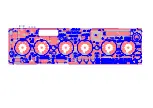
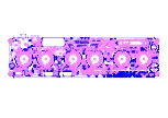
illustrations


and


check


the


type


of


the


capacitors.


"Good"


capacitor


"Bad"


capacitor


No


modifications


Capacitors


C13


and


C20


need


to


be


made.


needs


to


be


un

soldered.


The


clock


is


equipped


in


total


with


eight


of


this


100


nF


capacitors;


either


the


"left"


or


the


"right"


version.


The


possibility


of


a


failure


only


can


happens


on


C13


and


/


or


C20;


which


means


that


the


remaining


six


"bad"


capacitors


can


be


remain


soldered


in.


For


de

soldering


capacitor


C13


/


C20


please


do


the


following


task:


Heat


up


both


solder


pads


of


each


capacitor


simultaneous


with


the


help


of


a


fat


drop


of


solder


tin


and


pull


out


the


capacitors


with


tweezers.


Next


clean


all


pads


with


a


de

soldering


pump.


With


this


method


your


clock


is


temporarly


functional,


but


it


is


strongly


recommended


to


replace


C13


and


C20


with


100


nF


/


100


V


versions.


Furthermore


it


was


mentioned,


that


both


electrolyt


capacitors


C5


and


C6


are


driven


nearly


outside


their


voltage


range


(25V


each).


No


issues


were


reported


so


far,


anyway


it


is


recommeded


to


solder


both


electrolyt


capacitors


a


resistor


of


47


kohms


each


in


parallel


for


improved


voltage

symmetry.


On


request


the


manufacturer


offers


a


free


upgrade


set,


composed


of


2


x


ceramic


capacitors


100


nF


/


100


V


and


2


x


47


kohms


small


sized


resistors.


Please


contact


the


manufacturer


via


email


at


[email protected].


These


modifications


only


affect


clocks


up


to


serial

no.


JR

267


Starting


from


serial

no.


JR

268


adequate


improvements


has


been


made.


Summary of Contents for Jenny reloaded

Page 1: ...reit gemacht hat gilt nach VDE 0869 als Hersteller und ist verpflichtet bei der Weitergabe des Geräts alle Begleitpapiere mitzuliefern und auch sei nen Namen nebst Anschrift anzugeben Geräte die aus Bausätzen selbst zusammenge stellt werden sind sicherheitstechnisch wie ein industrielles Produkt zu betrachten Und nun meine Dame mein Herr befeuern Sie Ihre Lötstation und blättern Sie um Ausgabe 1 2...

Page 2: ...linke oder die rechte Ausführung Der Ausfall betrifft jedoch nur C13 und oder C20 d h dass die anderen sechs schlechten Kondensatoren in der Leiterplatte belassen werden können Zum Auslöten der Kondensatoren C13 C20 gehen Sie wie folgt vor Erhitzen Sie die beiden Lötaugen pro Kondensator gleichzeitig unter Zugabe von Lötzinn und ziehen Sie die Kondensatoren z B mit einer Pinzette heraus Danach öff...

Page 3: ...r the right version The possibility of a failure only can happens on C13 and or C20 which means that the remaining six bad capacitors can be remain soldered in For de soldering capacitor C13 C20 please do the following task Heat up both solder pads of each capacitor simultaneous with the help of a fat drop of solder tin and pull out the capacitors with tweezers Next clean all pads with a de solder...

Page 4: ...also not mismatch both inductors L2 and L3 with the 1 kohms resistors Please be also carefully when beding the crystal s leads Next is to assemble both diodes Note the polarity which is marked with a white ring on the diodes package The polarity of the six resistor arrays RN1 6 which are assembled next is negligable Next step is to assemble the USB jack Tip Solder one of the case s pads from the c...

Page 5: ...tören darin befinden sich Leiterbahnen Zum Schluss setzen wir den PLCC28 Sockel ein Bitte prüfen Sie lieber dreimal ob er richtig gepolt mit der Kerbe nach links unten eingesetzt ist bevor Sie ihn verlöten Er kann im Nachhinein nicht mehr ausgelötet werden ohne die Leiterplatte zu zerstören selbst mit einer professionellen Entlöt Station Brücken löten Solder jumpers Keine Gewalt beim Einsetzen No ...

Page 6: ...enden werden Rechts ist auch der korrekte Einbau des optionalen ASK Moduls dargestellt Schließen Sie die Leiterplatte an eine 5 V S pannungsversorgung an und beob achten Sie ob etwas ungewöhnliches passiert oder ein Bauteil warm wird Mes sen Sie sodann die Anodenspannung an den gekennzeichneten Punkten Sie sollte sich im Bereich um 47 V bewegen Ist alles in Ordnung trennen Sie die Leiterplatte wie...

Page 7: ... eloaded eloaded eloaded 5 Aufbau des Röhren Montage Tool Assembling the Tubes Mounting Tool Bitte ziehen Sie jetzt noch nicht die Schutzfolien von den Plexiglasplatten ab Please do not remove the protectiv covers from the Plexiglas frames yet 2 Tx M3 x 12 1 Tx M3 x 10 3 M3 x 6 M3x12 5 4 M3 x 20 6 Kreuzschl Pozidriv M2 5 x 6 M2 5 x 12 9 7 M3 x 30 8 10 Tx M3 x 12 Schlitz Slot 11 Anschlussdrähte lei...

Page 8: ... IV 11 15 11 15 11 15 11 15 11 15 VFD Cloc VFD Cloc VFD Cloc VFD Cloc VFD Clock J k J k J k J k Jenn enn enn enn enny r y r y r y r y reloaded eloaded eloaded eloaded eloaded 6 15 18 Ausrichten Adjust 17 19 21 22 20 Schräg abschneiden Cut angular Jetzt Röhren Montagetool zerlegen Disassemble tubes mounting tool now 23 16 Bitte nicht auseinanderbauen Please do not disassemble M3 x 6 M3 x 6 2 7 x 2 ...

Page 9: ...13 10 HV12 11 BLANK 13 GND 14 CLK 15 STROBE 16 HV11 12 HV10 17 HV9 18 HV8 19 HV7 20 HV6 21 HV5 22 HV4 23 HV3 24 HV2 25 HV1 26 VDD 28 DATA 27 R6 22k R6 22k C C C14 4n7 C14 4n7 RN2C RN2C R3 1k R3 1k H8 IV 15 H8 IV 15 RN6A RN6A R2 22k R2 22k J J C7 0u1 C7 0u1 RN1A RN1A C17 33p C17 33p C18 33p C18 33p a b c d e f g h H5 IV 11 a b c d e f g h H5 IV 11 G 2 c 3 g 7 b 5 FI 1 h 4 a 6 f 8 e 9 d 10 FI 11 RN3...

Page 10: ...2N7000 MosFet TO92 T1 T3 T4 T5 T6 5 RFD3055L MosFet DPAC T2 1 LED 5mm Pink LED7 LED8 2 LED 5mm Warm White LED9 LED10 2 Halbleiter Semicoductor Spacer 8 mm LED7 LED10 4 Sounder 42 ohms SND1 1 Drucktaster Switches S1 S4 4 EMV Drossel Inductor L1 1 47µH SMD Spule Inductor L4 1 Mini USB Buchse Jack BU1 1 Divers 3 5 mm Buchse 1 8 TRS Jack BU2 1 Mechanik Metall Distanz Spacer M3 x 6 18H2452 5 03 063 4 P...

Page 11: ......

Page 12: ......

Page 13: ......

Page 14: ......

Reviews: