Aufbau- und Montageanleitung IV
IV
IV
IV
IV-11/15
-11/15
-11/15
-11/15
-11/15 VFD Uhr „J
VFD Uhr „J
VFD Uhr „J
VFD Uhr „J
VFD Uhr „Jenn
enn
enn
enn
enny r
y r
y r
y r
y reloaded“
eloaded“
eloaded“
eloaded“
eloaded“
Assembly- and Mounting-Instructions IV
IV
IV
IV
IV-11/15
-11/15
-11/15
-11/15
-11/15 VFD Cloc
VFD Cloc
VFD Cloc
VFD Cloc
VFD Clock „J
k „J
k „J
k „J
k „Jenn
enn
enn
enn
enny r
y r
y r
y r
y reloaded“
eloaded“
eloaded“
eloaded“
eloaded“
– 4 –
Warm White Pink
Langer Draht = Anode,
bezeichnet mit „A“ auf der
Leiterplatte. Kurzer Draht =
Kathode, markiert mit „O“ auf
der Leiterplatte.
Long wire (Anode) is marked
with an „A“ on PCB, short
wire (Cathode) is marked
with an „O“ on PCB.
!
ENABLE
STEP-UP
CONVERTER
H - I
+
–
HV ca. 47 V
5,5 mm
R14 auf Unterseite auflöten • Solder R14 from bottom side
Wenn kein
Zeitzeichen-Empfänger
verwendet wird:
If no RTF receiver is
used:
RTF-SOURCE
B - C
und / and
POLARITY
D - F
Wenn das interne ASK-
Empfangs-Modul
verwendet wird:
If the internal ASK
receiver modul is used:
RTF-SOURCE
B - C
und / and
POLARITY
D - F
Wenn der externe DCF/
MSF-Empfänger
verwendet wird.
If the external DCF/MSF
receiver is used:
RTF-SOURCE
A - B
und / and
POLARITY
F - G
Wenn der externe Micro
GPS-Empfänger
verwendet wird.
If the external Micro-
GPS receiver is used:
RTF-SOURCE
A - B
und / and
POLARITY
D - F
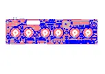
Bestücken Sie abschließend noch die verbleibenden Bauteile, besonders die hochkant
einzubauenden Widerstände R15 und R17 sowie R14, der auf der Unterseite aufgelötet
wird. Bauen die dann die IC’s richtig herum (!) in ihre Fassungen ein
und setzen Sie auf
der Unterseite einige Lötbrücken wie rechts dargestellt; z.B. H - I
. Achten Sie hier
besonders auf die Abbildungen sowie darauf, ob Sie einen Zeitzeichenempfänger
verwenden werden. Rechts ist auch der korrekte Einbau des optionalen ASK-
Moduls dargestellt.
Schließen Sie die Leiterplatte an eine 5 V S pannungsversorgung an und beob-
achten Sie, ob etwas ungewöhnliches passiert oder ein Bauteil warm wird. Mes-
sen Sie sodann die Anodenspannung an den gekennzeichneten Punkten. Sie
sollte sich im Bereich um 47 V bewegen. Ist alles in Ordnung,
trennen Sie die Leiterplatte wieder von der S tromversorgung.
Bitte machen Sie nicht weiter, solange Sie diese Spannung nicht
messen können sondern suchen Sie nach dem Fehler
.
Nachfolgend beginnen wir mit dem Aufbau des Röhren-Montage-
Tools, dem Einbau der Röhren und letztendlich dem Zusammen-
bau der kompletten Uhr.
DS18B20
Finally assemble the remaining parts, specially R15 and R17, which needs to be
mounted vertically and R14, which must be assembled from the solder side as shown
in the picture. Next assemble the IC’s and fit them in the correct position (note the notch
as polarity marking).
Now some solder jumpers needs to be made, e.g. H - I
. Specially
for the „coding“ of an used RTF receiver have a closer look at the pictures. It is
also shown the correct inserting postion for the optional ASK receiver module.
Now connect the board to a 5 V power source and check if something strange
happens, for exampe a part will run hot. Next pick up your multimeter and check
the Anodevoltage as shown in the picture. The reading should be in the range of
47 V. If every thing is o.k. disconnect the board from the power
source.
Please do not continue until the voltage reading is the given
range and check for the fault.
Following we will assemble the tubes mounting tool which helps
inserting the VFD tubes for exact allignment and at the final stage
we assemble the enclosure.
Die 8 mm LED-Abstandshalter vor dem
Einsetzen nicht vergessen!
Don’t forget to fit the 8 mm LED
spacers before assembling the LEDs.


