3
T
b
is is an A for no special
the
mm shaft.
-3. Piping
1.
short as possible. Normally,
the suction line should be the same dia
the pump
sucti
r, conditions
required minimum flow velocities may dictate otherwise.
bows or 45-degree elbows
e standard elbow. Avoid using
the complete pump from the base.
ounted on a firm foundation. The motors should be supported
S
Before operating the pump for the first time, fill it with liquid
for the initial start-up.
temporarily, enough liquid will
brication upon restarting. It
some liquid in the pump at time of shutdown.
been filled with liquid, check for direction
y
f
disas
result in premature
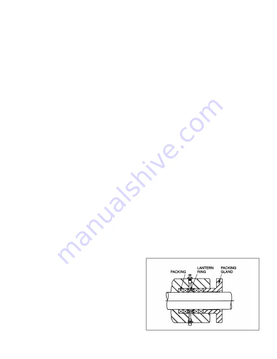
packing failure and possible damage to the shaft and gland.
he next letter indicates whether there are any special options
ng used in the pump, typically th
ei
options.
The next letter indicates the suction configuration. For this
pump an A is used designating a standard flanged pump.
The last letter indicates the drive configuration and
flange/shaft/seal size. In our close coupled pump nameplate
designates a 250mm flange and 45
C
2-1. INSTALLATION
-2. General
2
Accessibility to the pump and adequate clearance should be
prime considerations in any installation. Enough space should
surround the unit so that maintenance can be performed with
ease.
2
Suction piping should be as
meter as
on; howeve
such as high viscosity or
3
Long-sweep 90-degree el
should be used instead of th
suction piping loops, which trap air.
2.
Discharge piping diameter should generally be as large as
the discharge port unless fluid conditions indicate
otherwise.
3. An easily removable section of piping, at least twice as
long as the stator, should be mated to the discharge port.
This will allow the rotor and stator to be removed without
having to remove
2-4. Foundation
For maximum pump-driver unit life, each unit should be
mounted on a strong steel baseplate. The baseplate should be
m
on close-coupled configurations above 30 HP.
3-1. OPERATION
3-2. Initial Check
Before putting the pump into operation, the following items
should be checked to ensure that each piece of equipment is
installed correctly:
Electrical
connections.
Gauges and other instruments.
Pump rotation. Rotation is indicated on the pump
nameplate.
All valves should be open on both suction and discharge
sides of pump.
eal flush systems if required should be operational.
Double seals require flushing between faces.
CAUTION: This is a positive displacement pump. Do not
operate it against a closed valve.
3-3. Start-Up
CAUTION: DRY OPERATION IS HARMFUL TO THE PUMP!
Never allow the pump to operate without liquid, as dry
operation will cause premature wear of the stator and possible
damage. The liquid being pumped lubricates the stator.
1.
to lubricate the stator
Note:
If the pump is shut down
remain in the system to provide lu
is advisable to maintain the suction piping at a higher
elevation than the centerline of the pump in order to contain
2.
Once the pump has
of pump rotation by momentarily starting and stopping the
drive. See pump nameplate for correct rotation.
3.
Start seal flush water if so equipped.
4. Start
pump.
-4. Packing Leakage
The packed stuffing box is designed to control leakage, not stop
it completely. Leakage is necessary to reduce friction and
dissipate heat.
In a new pump, before the packing has had a chance to seat
properly, excessive leakage through the stuffing box is common.
Frequent adjustments of the packing gland may be necessar
during the first few hours of operation in order to compress and
seat the packing. See Section 4-3.
4-1. MAINTENANCE
4-2. General
The Moyno 2000 CC pump has been designed for a minimum o
maintenance, the extent of which is routine adjustment of the
packing. The pump is one of the easiest to maintain because the
main elements are very accessible and require few tools to
semble.
4-3. Packing Adjustment
Packing gland nuts (see Figure 4-1) should be evenly adjusted.
Overtightening the packing gland may
Summary of Contents for 2000 CC
Page 1: ...fCover Page Moyno 2000 CC Pumps...
Page 15: ...13...
Page 16: ...13 1 Seal Set Dimensions...
Page 17: ...14 1 TROUBLESHOOTING CHART...


