23
REPLACEMENT PARTS
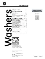
CONTROL BOX
Fig. 7
Part
Part Description
Qty.
Item No.
No.
1
0707403
Control Box (prior to S/N 18673)..............................................
1
1
0709049
Control Box (starting @ S/N 18674) .........................................
1
2
0307405
Injector Motor Plate ...................................................................
1
3
0501519
Tie, Nylon 4 in ...........................................................................
6
4
0502666
1/8 x 1/4 OD Tubing ..................................................................
AR
5
0706635
45CC Element Tube ...................................................................
2
6
0706634
15CC Element Tube ...................................................................
1
7
0707142
Rotor Assembly..........................................................................
3
8
0506589
Screw, 6-32 x 7/8"......................................................................
6
9
0504822
Screw, 8-32 x 1/2"......................................................................
12
10
0501353
Chemical Injector Motor ............................................................
3
11
0507314
Start Capacitor (3 uF).................................................................
1
12
0307422
Thermostat Bracket ....................................................................
1
13
0501450
Screw, 6-32 x 3/16"....................................................................
4
14
0507323
Thermostat..................................................................................
1
15
0503592 Label,
Ground ............................................................................
1
15
0501403
Screw, Ground, 10-32 x 3/4"......................................................
2
15
0501533
Nut, Ground, 10-32 ....................................................................
2
15
0501493
Washer, Lock, Ground, #10 .......................................................
2
15
0501472
Washer, Flat, Ground .................................................................
3
16
0503648
Screw, 8-32 x 5/16"....................................................................
2
17
0503647
Strain Relief Bushing (Medium)................................................
1
18
0503574
Strain Relief Bushing (Small) ....................................................
2
19
0501887
7/8" Button Plug.........................................................................
1
20
0507372
Power Cord.................................................................................
1
21
0503749
Terminal Board...........................................................................
2
22
0701933
Water/Heater Cam c/w Set Screw ..............................................
1
23
0501397
Set Screw, 6-40 x 3/16"..............................................................
1
24
0501379
Float Switch ...............................................................................
1
25
0307369
Nut Plate for Float Switch (starting @ S/N 18674)...................
1
26
0501433
Screw, 4-40 x 5/8"......................................................................
2
27
0501411
Screw, 10-32 x 1/4"....................................................................
8
28
0309053
Float Switch Support (starting @ S/N 18674)...........................
1
29
0503642
Label, 2.5 Amp Fuse ..................................................................
1
30
0503693
Label, Switch Up........................................................................
1
31
0501373
3-Position Switch .......................................................................
1
32
0501412
Screw, 10-32 x 3/8"....................................................................
8
33
0507470
Label, Injector Prime..................................................................
1
Summary of Contents for DF
Page 4: ...THIS PAGE INTENTIONALLY LEFT BLANK 2 ...
Page 18: ...THIS PAGE INTENTIONALLY LEFT BLANK 16 ...
Page 19: ...17 REPLACEMENT PARTS REPLACEMENT PARTS ...
Page 32: ...30 REPLACEMENT PARTS Figure 11 Sanitizer Plumbing 8 7 6 5 3 2 1 11 12 9 13 14 15 16 4 9 10 ...
Page 36: ...34 REPLACEMENT PARTS Figure 13 Wash Pump 1 2 3 4 5 6 5 7 9 8 8 10 11 12 13 14 16 15 17 18 ...
Page 38: ...36 REPLACEMENT PARTS Figure 14 Drive Complete 2 3 4 5 6 7 8 1 4 ...
Page 40: ...38 REPLACEMENT PARTS 1 3 2 4 5 6 5 7 8 Figure 15 Cleaning Accessories ...
Page 45: ......
Page 46: ......