background image

- 3 - 

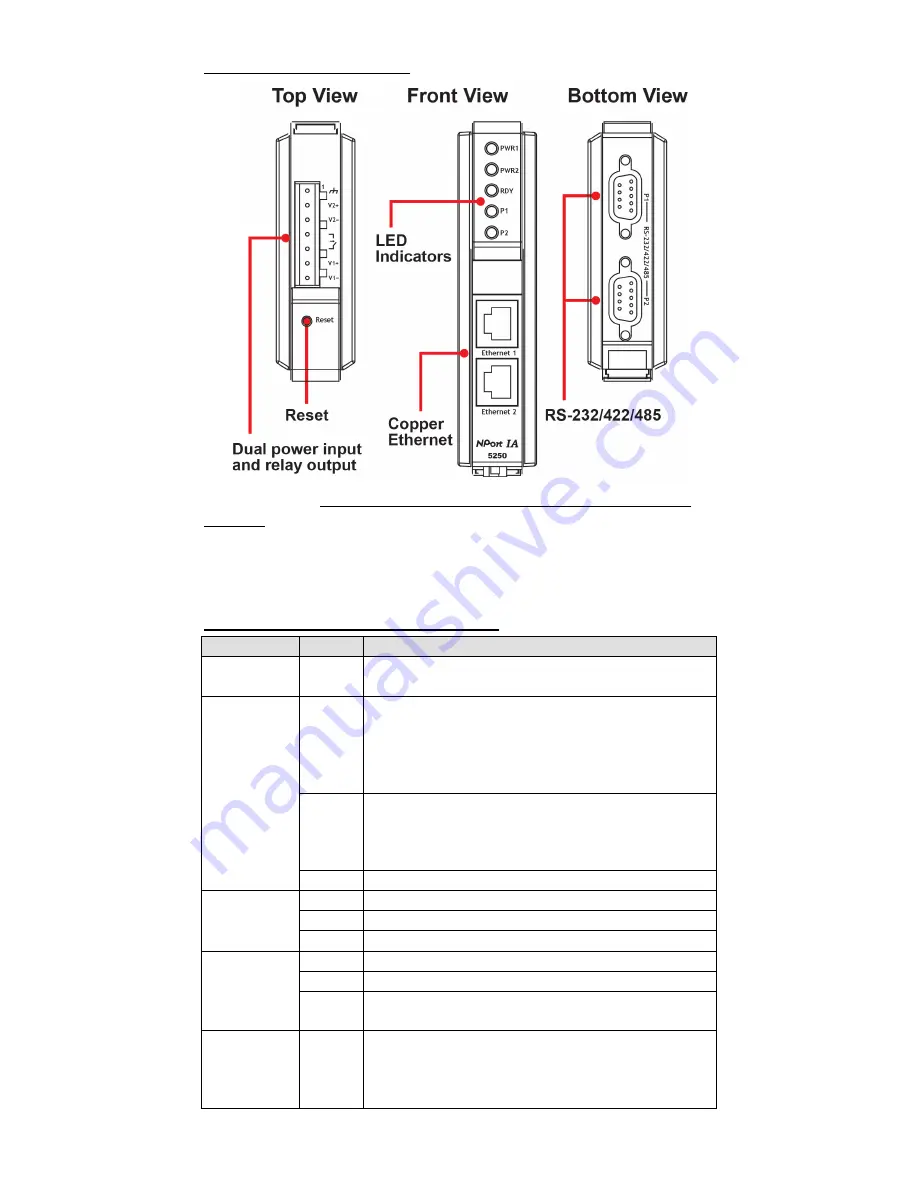
NPort IA5250 Appearance 


Reset Button—

Press the Reset button for 5 seconds to load factory 

defaults. 

Use a pointed object, such as a straightened paper clip or 

toothpick, to press the reset button. This will cause the Ready LED to blink 
on and off. The factory defaults will be loaded once the Ready LED stops 
blinking (after about 5 seconds). At this point, you should release the 
reset button. 

NPort IA LED Indicators (front panel) 

Name 

Color  Function 

PWR1,PWR2 

Red 

Power is being supplied to power input PWR1, 
PWR2. 

Ready 

Red 

Steady on: Power is on, and the NPort IA is 
booting up. 
Blinking: Indicates an IP conflict, the DHCP or 
BOOTP server did not respond properly, or a relay 
output occurred. 

Green 

Steady on: Power is on, and the NPort IA is 
functioning normally. 
Blinking: The device server has been located by 
the Administrator’s Location function. 

Off 

Power is off, or a power-error condition exists. 

Ethernet 

Orange  10 Mbps Ethernet connection. 

Green  100 Mbps Ethernet connection. 

Off 

Ethernet cable is disconnected, or has a short. 

P1, P2 

Orange  Serial port is receiving data. 

Green  Serial port is transmitting data. 

Off 

No data is being transmitted or received through 
the serial port. 

FX 

Orange 

Steady on: Ethernet fiber connection, but port is 
idle. 
Blinking: Fiber port is transmitting or receiving 
data. 

Summary of Contents for NPort IA 5250 series

Page 1: ...oxa Americas Toll free 1 888 669 2872 Tel 1 714 528 6777 Fax 1 714 528 6778 Moxa China Shanghai office Toll free 800 820 5036 Tel 86 21 5258 9955 Fax 86 21 5258 5505 Moxa Europe Tel 49 89 3 70 03 99 0 Fax 49 89 3 70 03 99 99 Moxa Asia Pacific Tel 886 2 8919 1230 Fax 886 2 8919 1231 Moxa India Tel 91 80 4172 9088 Fax 91 80 4132 1045 2016 Moxa Inc All rights reserved ...

Page 2: ...s come with a compact and rugged DIN rail mountable casing Package Checklist Before installing NPort IA device servers verify that the package contains the following items 1 NPort IA series device server Documentation and software CD NPort IA series quick installation guide Optional Accessories DR 4524 5W 2A DIN rail 24 VDC power supply with universal 85 to 264 VAC input DR 75 24 75W 3 2A DIN rail...

Page 3: ...nd the NPort IA is booting up Blinking Indicates an IP conflict the DHCP or BOOTP server did not respond properly or a relay output occurred Green Steady on Power is on and the NPort IA is functioning normally Blinking The device server has been located by the Administrator s Location function Off Power is off or a power error condition exists Ethernet Orange 10 Mbps Ethernet connection Green 100 ...

Page 4: ...N rail or mounted on a wall The two sliders on the NPort IA s rear panel serve a dual purpose For wall mounting both sliders should be extended For DIN rail mounting start with one slider pushed in and the other slider extended After attaching the NPort IA on the DIN rail push the extended slider in to lock the device server to the rail The two placement options are illustrated in the accompanying...

Page 5: ...ND GND 6 DSR 7 RTS 8 CTS 9 4W 2W RS 485 RS 422 Terminal Block Pinouts PIN RS 485 2W RS 422 RS 485 4W 1 TxD B 2 TxD A 3 Data B RxD B 4 Data A RxD A 5 GND Four cables are available as optional accessories that can be used to connect the NPort IA to RS 232 serial devices For your convenience we show precise cable wiring diagrams for each of the two cables Female DB9 to Male DB9 ...

Page 6: ...t Communication Devices are to be mounted in an IP54 enclosure and used in an area with a pollution degree of not more than 2 as defined by IEC 60664 1 A 4 mm2 conductor must be used when a connection to the external grounding screw is utilized Conductors suitable for use in an ambient temperature of 114 C must be used for the Power Supply Terminal Provisions shall be made either in the apparatus ...

Reviews: